DYNAMIC REAR STEERING ACTUATOR INSTALLATION

PROCEDURE
-
INSTALL REAR STEERING LINK ASSEMBLY
-
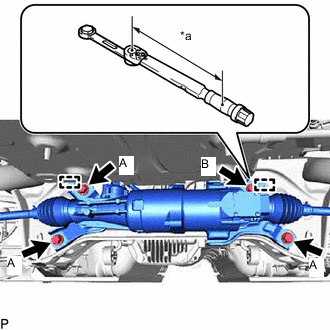
*a Torque Wrench Fulcrum Length Align the 2 guide pins with the rear suspension member sub-assembly and install the rear steering link assembly with the 4 bolts.
- Torque:
- Bolt A
- 97 N*m { 989 kgf*cm, 72 ft.*lbf }
Tech Tips
Temporarily tighten the bolt B.
-
Using a ball joint lock nut wrench, fully tighten the bolt B.
- Torque:
- Specified tightening torque
- 97 N*m { 989 kgf*cm, 72 ft.*lbf }
Tech Tips
-
Calculate the torque wrench reading when changing the fulcrum length of the torque wrench.
-
When using a ball joint lock nut wrench (fulcrum length of 150 mm (5.906 in.)) + torque wrench (fulcrum length of 255 mm (10.039 in.)): 61.1 N*m (623 kgf*cm, 45 ft.*lbf)
-
Engage the wire harness clamp and install the grommet.
-
Install the nut.
- Torque:
- 5.4 N*m { 55 kgf*cm, 48 in.*lbf }
-
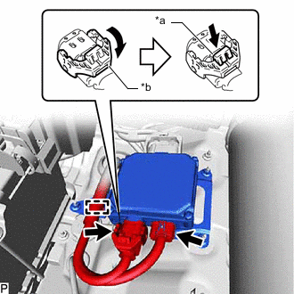
*a Lock of the Lock Lever *b Lock Lever Connect the 2 connectors to the rear steering control ECU.
Tech Tips
When connecting the connector with lock lever, return the lock lever to its original position and securely push in the lock of the lock lever as shown in the illustration.
-
Engage the clamp.
-
-
INSTALL EXHAUST TAILPIPE ASSEMBLY
-
CONNECT REAR STEERING TIE ROD ASSEMBLY LH
-
Install the rear steering tie rod assembly LH to the rear axle carrier sub-assembly with a new nut.
- Torque:
- 118 N*m { 1203 kgf*cm, 87 ft.*lbf }
-
Connect the skid control sensor wire LH to the rear steering tie rod assembly LH with the bolt.
- Torque:
- 8.5 N*m { 87 kgf*cm, 75 in.*lbf }
-
-
CONNECT REAR STEERING TIE ROD ASSEMBLY RH
Tech Tips
Perform the same procedure as for the LH side.
-
INSTALL REAR WHEELS
-
INSTALL NO. 1 FLOOR UNDER COVER
-
INSTALL BATTERY CARRIER CATCH BRACKET SUB-ASSEMBLY
-
INSTALL LOWER INNER LUGGAGE COMPARTMENT TRIM COVER
-
INSTALL LUGGAGE COMPARTMENT FLOOR MAT
-
INSTALL TOOL BOX
-
CONNECT CABLE TO NEGATIVE AUXILIARY BATTERY TERMINAL
Note
When disconnecting the cable, some systems need to be initialized after the cable is reconnected.
-
INSTALL LUGGAGE COMPARTMENT MAT SUB-ASSEMBLY
-
INSPECT AND ADJUST REAR WHEEL ALIGNMENT
-
PERFORM DYNAMIC REAR STEERING SYSTEM CALIBRATION