BRAKE CONTROL POWER SUPPLY REMOVAL
CAUTION / NOTICE / HINT
The necessary procedures (adjustment, calibration, initialization, or registration) that must be performed after parts are removed, installed, or replaced during brake control power supply with bracket assembly removal/installation are shown below.
| Replaced Part or Performed Procedure | Necessary Procedure | Effect/Inoperative Function when Necessary Procedure not Performed | Link |
|---|---|---|---|
| Auxiliary battery terminal is disconnected/reconnected | Memorize steering angle neutral point | LKA/LDA system (for Mono camera type) | for Stereo Camera type: Click here for Mono Camera type: Click here |
| Lane control system (for Stereo camera type) | |||
| Parking support brake system* | |||
| Pre-collision system (for Stereo camera type) | |||
| Pre-collision system (for Mono camera type) | |||
| Adaptive high beam system | |||
Lighting system (EXT) |
|||
| Variable gear ratio steering system | |||
| Parking assist monitor system | |||
| Panoramic view monitor system | |||
| Initialize rear door sunshade system | Rear door sunshade system | ||
| Initialize power trunk lid system | Power trunk lid system |
Click here Click here
CAUTION / NOTICE / HINT
Note
While the auxiliary battery is connected, even if the power switch is off, the brake control system activates when the brake pedal is depressed or any door courtesy switch is turned on. Therefore, when servicing brake system components, do not depress the brake pedal or open/close the doors while the auxiliary battery is connected.
PROCEDURE
-
PRECAUTION
Note
After turning the power switch off, waiting time may be required before disconnecting the cable from the negative (-) auxiliary battery terminal. Therefore, make sure to read the disconnecting the cable from the negative (-) auxiliary battery terminal notices before proceeding with work.
-
REMOVE LUGGAGE COMPARTMENT MAT SUB-ASSEMBLY
-
DISCONNECT CABLE FROM NEGATIVE AUXILIARY BATTERY TERMINAL
-
REMOVE LUGGAGE COMPARTMENT FLOOR MAT
-
REMOVE LUGGAGE COMPARTMENT TRIM COVER LH
-
REMOVE LUGGAGE COMPARTMENT TRIM COVER RH
-
REMOVE TOOL BOX
-
REMOVE INNER LOWER LUGGAGE COMPARTMENT TRIM COVER
-
REMOVE ROPE HOOK ASSEMBLY
-
REMOVE REAR FLOOR FINISH PLATE
-
REMOVE SIDE TRIM BOX
-
REMOVE REAR LUGGAGE COMPARTMENT TRAY BRACKET RH
-
REMOVE BRAKE CONTROL POWER SUPPLY WITH BRACKET ASSEMBLY
CAUTION:
After removing the brake control power supply with bracket assembly from the vehicle, there may be an electrical charge left in the internal capacitor. If planning to inspect the inside of the brake control power supply with bracket assembly, leave it as is for more than 24 hours (to discharge it) after removing it from the vehicle. Then, perform the inspection.
-
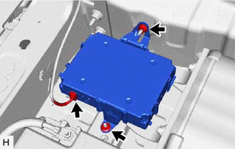
Disconnect the brake control power supply connector.
-
Remove the 2 nuts and brake control power supply with bracket assembly from the vehicle body.
-