REAR SHOCK ABSORBER INSTALLATION

CAUTION / NOTICE / HINT
Tech Tips
-
Use the same procedure for the RH and LH side.
-
The following procedure is for the LH side.
PROCEDURE
-
INSTALL REAR SHOCK ABSORBER ASSEMBLY LH
-
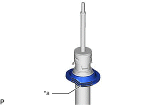
*a Depression Install the rear lower coil spring insulator LH to the rear shock absorber assembly LH.
-
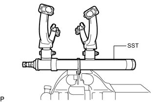
Secure SST in a vise.
- SST
- 09727-30022
-
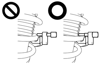
Attach the hooks of each SST arm across the diameter of the coil spring.
CAUTION:
-
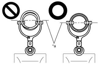
*a Rear Coil Spring Diameter Do not perform the work without checking to make sure that the claws of the hooks are securely engaged.
-
It could cause the hook to slip off and the spring to fly out, which could result in an injury.
-
Do not install SST to the rear coil spring unless its top and bottom hook distance is set to the widest condition.
-
It could cause the hook to slip off and the spring to fly out, which could result in an injury.
-
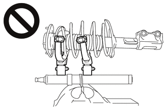
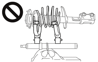
Do not install SST when the distances between the SST arms or the number of coils of the coil spring between the hooks are not the same.
-
It could cause the hook to slip off and the spring to fly out, which could result in an injury.
-
-
Install the stopper pins to the hooks of SST.
CAUTION:
-
Do not perform the work if the stopper pin is not securely installed.
-
It could cause the hook to slip off and the spring to fly out, which could result in an injury.
-
-
Using SST, compress the coil spring.
CAUTION:
-
While compressing the spring, if the front coil spring starts to bend into a bow shape, do not continue the work.
-
It could cause the hook to slip off and the spring to fly out, which could result in an injury.
-
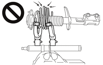
Do not compress the springs so far that the coils of the springs touch each other.
-
It could cause the hook to slip off and the spring to fly out, which could result in an injury.
-
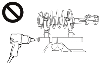
Do not use an impact wrench.
-
The threads may be stripped, or the sudden compression may result in slack that causes the hooks to slip off, causing the spring to fly out and possibly resulting in injury.
-
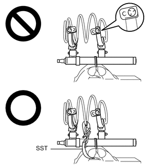
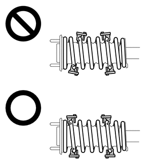
If a stopper pin touches the coil spring while using SST, remove the stopper pin and continue with the procedure.
-
If a stopper pin is removed, install SST as shown in the illustration.
-
If a hook disengages from the coil spring, the coil spring may fly out, resulting in injury.
- SST
- 09727-00110
-
-
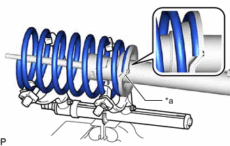
*a Depression Install the rear coil spring LH to the rear shock absorber assembly LH.
Note
Make sure that the end of the rear coil spring is positioned in the depression of the rear lower coil spring insulator LH.
-
Install the rear No. 1 spring bumper LH to the rear support assembly suspension LH.
-
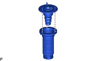
Install the rear upper coil spring insulator LH to the rear support assembly suspension LH as shown in the illustration.
-
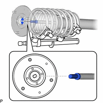
Install the rear support assembly suspension LH to the rear shock absorber assembly LH.
Note
Match the shape of the rear shock absorber assembly support ring end to the shape of the rear support assembly suspension LH.
-
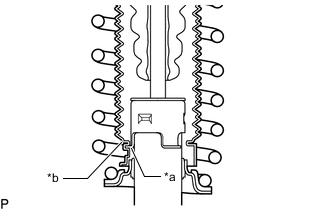
*a Rear Shock Absorber Assembly LH Claw *b End of Rear Upper Coil Spring Insulator LH Turn the rear support assembly suspension LH 120° or more to engage the end of the rear upper coil spring insulator LH to the rear shock absorber assembly LH claws.
Note
-
Make sure that the end of the rear upper coil spring insulator LH is engaged securely to the 3 rear shock absorber assembly LH claws.
-
Be careful not to deform the bellows of the rear upper coil spring insulator LH.
-
Keep the rear upper coil spring insulator LH free of oil and grease.
-
-
Temporarily tighten a new lock nut.
-
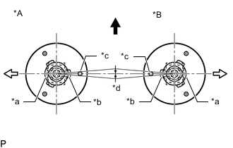
*A for LH Side *B for RH Side *a Rear Shock Absorber Assembly LH Bushing Large-diameter Side *b Rear Shock Absorber Assembly LH Bushing Small-diameter Side *c Front Suspension Support Assembly LH Stud Bolt *d 0°+/-2° 
Front of the Vehicle 
Outside of the Vehicle Adjust the rear support assembly suspension LH so that the bolts come to the positions as shown in the illustration, and remove SST from the rear coil spring.
Note
-
Do not use an impact wrench. It will damage SST.
-
Make sure that the width across flat on the rear shock absorber piston rod end is located parallel to the rear shock absorber bushing.
-
Make sure of the direction of the rear suspension support assembly when removing SST.
-
-
-
TEMPORARILY TIGHTEN REAR SHOCK ABSORBER WITH COIL SPRING
-

Temporarily tighten the washer and rear shock absorber with coil spring with a new nut.
-
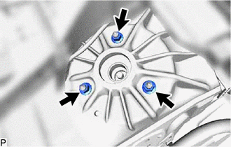
Temporarily tighten the rear suspension spring support reinforcement and rear shock absorber with coil spring with the 3 nuts.
Tech Tips
If the nut is hard to see, use a mirror.
-
-
CONNECT SKID CONTROL SENSOR WIRE LH
-
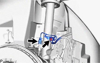
Install the skid control sensor wire LH with the nut.
- Torque:
- 6.0 N*m { 61 kgf*cm, 53 in.*lbf }
-
Connect the connector.
-
-
TEMPORARILY TIGHTEN REAR STABILIZER LINK ASSEMBLY LH
-
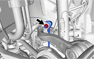
Temporarily tighten the rear stabilizer link assembly LH to the rear stabilizer bar with the nut.
-
Temporarily tighten the rear stabilizer link assembly LH to the rear No. 2 suspension arm assembly LH with the bolt and nut.
-
-
STABILIZE SUSPENSION
-
TIGHTEN REAR SHOCK ABSORBER WITH COIL SPRING
-
Fully tighten the nut.
- Torque:
- 110 N*m { 1122 kgf*cm, 81 ft.*lbf }
-
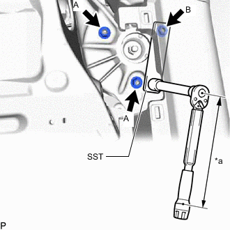
*a Torque Wrench Fulcrum Length Fully tighten the 2 nuts A.
- Torque:
- 40 N*m { 408 kgf*cm, 30 ft.*lbf }
Tech Tips
If the nut is hard to see, use a mirror.
-
Using SST, fully tighten the nut B.
- SST
- 09249-37010
- Torque:
- Specified tightening torque
- 40 N*m { 408 kgf*cm, 30 ft.*lbf }
Tech Tips
-
Calculate the torque wrench reading when changing the fulcrum length of the torque wrench.
-
When using SST (fulcrum length of 100 mm (3.937 in.)) + torque wrench (fulcrum length of 180 mm (7.087 in.)): 25.7 N*m (262 kgf*cm, 19 ft.*lbf)
-
If the nut is hard to see, use a mirror.
-
Fully tighten the lock nut.
- Torque:
- 27.5 N*m { 280 kgf*cm, 20 ft.*lbf }
Note
Perform this step only when the rear shock absorber with coil spring has been disassembled.
-
-
INSTALL REAR SHOCK ABSORBER CAP LH
-
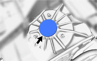
Install the rear shock absorber cap LH.
-
-
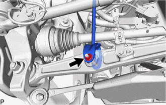
TIGHTEN REAR STABILIZER LINK ASSEMBLY LH
-
Fully tighten the nut.
Tech Tips
If the ball joint turns together with the nut, use a 6 mm hexagon wrench to hold the stud bolt.
- Torque:
- 89 N*m { 908 kgf*cm, 66 ft.*lbf }
-
Fully tighten the nut.
- Torque:
- 24 N*m { 245 kgf*cm, 18 ft.*lbf }
-
-
INSTALL REAR WHEEL HOUSE LINER LH
-
INSTALL ROCKER PANEL MOULDING PROTECTOR LH
-
INSTALL REAR WHEEL
-
INSTALL PACKAGE TRAY TRIM SIDE COVER LH
-
INSTALL NO. 1 CENTER SPEAKER GRILLE SUB-ASSEMEBLY
-
INSTALL PACKAGE TRAY TRIM GARNISH LH
-
INSTALL PACKAGE TRAY TRIM GARNISH RH
Tech Tips
Use the same procedure described for the LH side.
-
INSPECT AND ADJUST REAR WHEEL ALIGNMENT
-
PERFORM INITIALIZATION
Parking support brake system Panoramic view monitor system Parking assist monitor system
-
Dynamic rear steering system
w/ Dynamic Rear Steering System:
Automatic headlight beam level control system -
-
ADJUST HEADLIGHT AIMING