CAUTION / NOTICE / HINT
-
Use the same procedure for the RH and LH side.
-
The following procedure is for the LH side.
PROCEDURE
- Click here
TEMPORARILY TIGHTEN LOWER NO. 2 SUSPENSION ARM ASSEMBLY LH
-
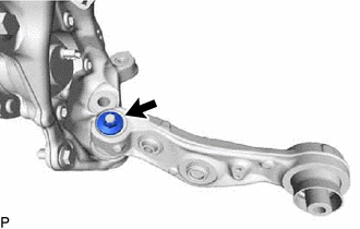
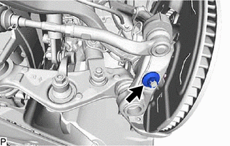
Temporarily tighten the lower No. 2 suspension arm assembly LH to the steering knuckle assembly LH with the nut.
-

Bolt 
Nut Insert the bolt from the back of the vehicle. Then temporarily tighten the lower No. 2 suspension arm assembly LH with the nut.
-
- Click here
CONNECT STEERING KNUCKLE ASSEMBLY LH
- Click here
CONNECT TIE ROD ASSEMBLY LH
- Click here
TEMPORARILY TIGHTEN FRONT SHOCK ABSORBER ASSEMBLY LH (w/o Air Suspension)
-
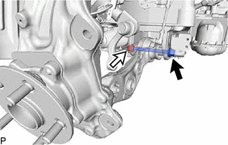
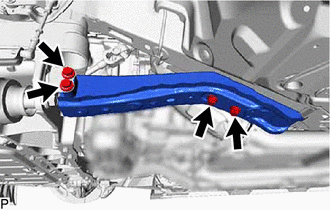
Bolt Nut Temporarily tighten the front shock absorber assembly LH to the lower No. 2 suspension arm assembly LH with the bolt and nut.
Note:
-
Insert the bolt from the rear of the vehicle.
-
Because the nut has its own stopper, do not turn the nut. Tighten the bolt with the nut secured.
-
-
- Click here
TEMPORARILY TIGHTEN FRONT PNEUMATIC CYLINDER WITH SHOCK ABSORBER ASSEMBLY LH (w/ Air Suspension)
Tip:Perform the same procedure as for the front shock absorber assembly LH.
- Click here
CONNECT FRONT STABILIZER LINK ASSEMBLY LH
- Click here
CONNECT FRONT HEIGHT CONTROL SENSOR SUB-ASSEMBLY LH
- Click here
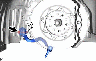
INSTALL FRONT DISC LH
-
for 6-Pot Caliper:
-
except 6-Pot Caliper:
-
- Click here
CONNECT DISC BRAKE CYLINDER ASSEMBLY LH
- Click here
TEMPORARILY TIGHTEN FRONT LOWER SUSPENSION ARM ASSEMBLY LH
-
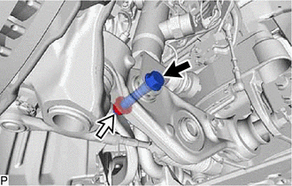
Bolt Nut Insert the bolt from the front of the vehicle. Temporarily install the front lower suspension arm assembly LH with the nut.
-
Temporarily tighten the front lower suspension arm assembly LH to the steering knuckle assembly LH with the nut.
-
- Click here
STABILIZE SUSPENSION
- Click here
FULLY TIGHTEN FRONT SHOCK ABSORBER ASSEMBLY LH (w/o Air Suspension)
-
Fully tighten the front shock absorber assembly LH bolt.
110 N*m 1122 kgf*cm 81 ft.*lbf Note:Because the nut has its own stopper, do not turn the nut. Tighten the bolt with the nut secured.
-
- Click here
FULLY TIGHTEN FRONT PNEUMATIC CYLINDER WITH SHOCK ABSORBER ASSEMBLY LH (w/ Air Suspension)
Tip:Perform the same procedure as for the front shock absorber assembly LH.
- Click here
FULLY TIGHTEN LOWER NO. 2 SUSPENSION ARM ASSEMBLY LH
-
Tighten the installation bolt of the lower No. 2 suspension arm assembly LH.
130 N*m 1326 kgf*cm 96 ft.*lbf -
Tighten the installation nut of the steering knuckle assembly LH.
145 N*m 1479 kgf*cm 107 ft.*lbf Note:Further tighten the nut up to 60° if the holes for the clip are not aligned.
-
Install a new clip.
-
- Click here
FULLY TIGHTEN FRONT LOWER SUSPENSION ARM ASSEMBLY LH
-
Tighten the installation bolt of the front lower suspension arm assembly LH.
130 N*m 1326 kgf*cm 96 ft.*lbf -
Tighten the installation nut of the steering knuckle assembly LH.
145 N*m 1479 kgf*cm 107 ft.*lbf Note:Further tighten the nut up to 60° if the holes for the clip are not aligned.
-
Install a new clip.
-
- Click here
INSTALL REAR LOWER ARM MOUNTING REINFORCEMENT SUB-ASSEMBLY LH
-
Install the rear lower arm mounting reinforcement sub-assembly LH with the 4 bolts.
16 N*m 163 kgf*cm 12 ft.*lbf
-
- Click here
INSTALL ENGINE SIDE COVER LH
-
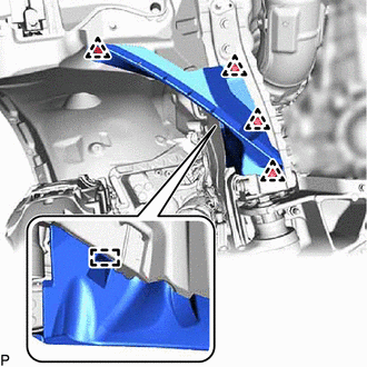
Install the engine side cover LH with the 4 clips and clamp.
-
- Click here
INSTALL NO. 2 ENGINE UNDER COVER ASSEMBLY
-
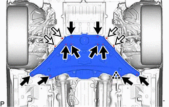
Bolt Screw Install the No. 2 engine under cover assembly with the 10 new bolts, 4 screws and clip.
Bolt 7.9 N*m 81 kgf*cm 70 in.*lbf
-
- Click here
INSTALL TRANSMISSION UNDER COVER
- Click here
INSTALL FRONT WHEEL
- Click here
CONNECT BRAKE BOOSTER PUMP CONNECTOR
- Click here
INSPECT AND ADJUST FRONT WHEEL ALIGNMENT
- Click here
INSPECT AND ADJUST VEHICLE HEIGHT (w/ Air Suspension)
- Click here
PERFORM INITIALIZATION
Parking support brake system Panoramic view monitor system Parking assist monitor system Variable gear ratio steering system
- w/o Air Suspension System:
-
Automatic headlight beam level control system
- Click here
ADJUST HEADLIGHT AIMING