CAUTION / NOTICE / HINT
The necessary procedures (adjustment, calibration, initialization, or registration) that must be performed after parts are removed, installed, or replaced during the front lower suspension arm removal/installation are shown below.
| Necessary Procedure After Parts Removed/Installed/Replaced | ||||||||||||||||||||||
|---|---|---|---|---|---|---|---|---|---|---|---|---|---|---|---|---|---|---|---|---|---|---|
|
-
When the brake pedal is first depressed after replacing the brake pads or pushing back the disc brake piston, DTC C1341, C1342, C1343 and/or C1344 may be stored. As there is no malfunction, clear the DTCs.
-
While the auxiliary battery is connected, even if the power switch is off, the brake control system activates when the brake pedal is depressed or any door courtesy switch is turned on. Therefore, when servicing, do not depress the brake pedal or open/close the doors while the auxiliary battery is connected.
-
Be sure to read the "PRECAUTION" thoroughly before servicing.
-
Use the same procedure for the RH and LH side.
-
The following procedure is for the LH side.
PROCEDURE
- Click here
ADJUST STANDARD VEHICLE HEIGHT
Tip:Check the vehicle condition when operating to the standard vehicle height setting.
-
Perform the work with the vehicle stopped on a flat surface.
-
Make sure the hood is closed.
-
Make sure the luggage compartment door closed
-
Set the shift lever to P.
-
Make sure the courtesy lights are not on.
-
Do not depress the brake pedal.
-
Perform height adjust from outside of the vehicle to avoid vehicle height changes due when getting out of the vehicle.
-
Adjust the air pressure in the tires.
-
Record the vehicle setting conditions on the multi-information display.
-
Get out of the vehicle and bounce the vehicle up and down at the corners to stabilize the suspension.
-
From the outside of the vehicle, select access mode and turn it off via the vehicle setting conditions on the multi-information display.
-
Operate the height control switch from outside the vehicle and adjust the vehicle height to HIGH
-
After vehicle height control is completed, operate the height control switch from outside the vehicle and return the vehicle height to NORMAL.
-
After vehicle height control is completed, select vehicle height control mode and turn it off via the vehicle setting conditions on the multi-information display.
-
- Click here
INSPECT TIRES
- Click here
MEASURE VEHICLE HEIGHT
- Click here
INSPECT CAMBER
Note:Inspect while the vehicle is unloaded.
-
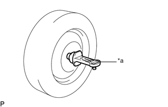
*a Camber-caster-kingpin Gauge Install a camber-caster-kingpin gauge.
-
w/ Air suspension:
Inspect the camber.
Camber (Unloaded Vehicle) Item Camber Inclination Right-left Difference for 2WD w/ Dynamic Rear Steering -1°25' +/-45' (-1.42° +/-0.75°) 0°30' (0.50°) or less w/o Dynamic Rear Steering -1°25' +/-45' (-1.42° +/-0.75°) 0°30' (0.50°) or less for AWD - -1°14' +/-45' (-1.23° +/-0.75°) 0°30' (0.50°) or less Tip:Camber is not adjustable. If the measurement is not within the specified range, inspect the suspension parts for damage and/or wear, and replace them if necessary.
-
w/o Air suspension:
Inspect the camber.
Camber (Unloaded Vehicle) Item Camber Inclination Right-left Difference for 2WD w/o Dynamic Rear Steering -1°06' +/-45' (-1.10° +/-0.75°) 0°30' (0.50°) or less for AWD w/o Dynamic Rear Steering -0°55' +/-45' (-0.92° +/-0.75°) 0°30' (0.50°) or less Tip:Camber is not adjustable. If the measurement is not within the specified range, inspect the suspension parts for damage and/or wear, and replace them if necessary.
-
- Click here
INSPECT TOE-IN
Note:Inspect while the vehicle is unloaded.
-
Bounce the vehicle up and down at the corners to stabilize the suspension.
-
Release the parking brake and move the shift lever to N.
-
Push the vehicle straight ahead approximately 5.0 m (16.4 ft.). (Step A)
-
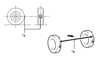
*a Tread Center Mark *b Dimension B 
Front of the Vehicle Put tread center marks on the rearmost points of the rear wheels and measure the distance between the marks (dimension B).
-
Slowly push the vehicle straight ahead to cause the rear wheels to rotate 180°. Use the rear tire valve as a reference point.
Tip:Do not allow the wheels to rotate more than 180°. If the wheels rotate more than 180°, perform the procedure from step A again.
-
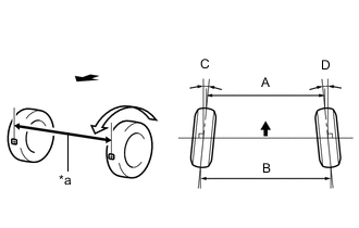
*a Dimension A Front of the Vehicle Measure the distance between the tread center marks on the front of the rear wheels (dimension A).
Toe-in (Unloaded Vehicle) Specified Condition C + D: 0°14' +/- 0°09' (0.23° +/- 0.15°)
B - A: 3.0 +/- 2.0 mm (0.1181 +/- 0.0787 in.)
Tip:Measure "B - A" only when "C + D" cannot be measured.
If the toe-in is not within the specified range, adjust it at the toe control link sub-assembly.
-
- Click here
ADJUST TOE-IN (w/o Dynamic Rear Steering)
-
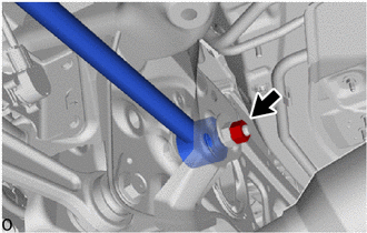
Loosen the nut of the toe control link sub-assembly (on the rear suspension member sub-assembly side).
Note:Hold the toe adjust cam sub-assembly while rotating the nut.
-
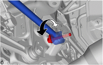
Rotate the toe adjust cam sub-assembly to adjust the toe-in.
Toe-in (Unloaded Vehicle) Specified Condition C + D: 0°14' +/- 0°09' (0.23° +/- 0.15°)
B - A: 3.0 +/- 2.0 mm (0.1181 +/- 0.0787 in.)
Tip:
-
Perform adjustments so that the value is as close as possible to the median of the specified range.
-
Rotating the toe adjust cam sub-assembly by one notch changes the toe by approximately 4.6 mm (0.181 in.).
-
-
Tighten the nut of the toe control link sub-assembly (on the rear suspension member sub-assembly side).
78 N*m 795 kgf*cm 58 ft.*lbf Note:Hold the toe adjust cam sub-assembly while rotating the nut.
-
- Click here
ADJUST TOE-IN (w/ Dynamic Rear Steering)
Note:If any underbody rear suspension parts are removed and installed, replaced or adjusted, the steering wheel may become off center.
Therefore, perform neutral point memorization and motor rotation angle sensor calibration.
-
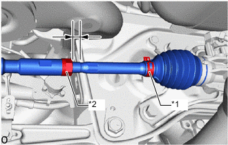
*1 Steering Rack Boot Clip *2 Lock Nut Make sure that the thread length of the right and left steering rack ends are approximately the same.
Standard Difference 1.5 mm (0.0591 in.) or less -
Remove the steering rack boot clips.
-
Loosen the tie rod assembly lock nuts.
-
Adjust the steering rack ends if the difference in thread length between the right and left steering rack ends is not within the specified range.
-
If the toe-in measurement is greater than the specified range (too much toe-in), shorten the longer steering rack end so that the length difference is within the specified range.
-
If the toe-in measurement is less than the specified range (too much toe-out), lengthen the shorter steering rack end so that the length difference is within the specified range.
-
Measure the toe-in.
-
-
Turn the right and left steering rack ends by an equal amount to adjust the toe-in.
Toe-in (Unloaded Vehicle) Specified Condition C + D: 0°14' +/- 0°09' (0.23° +/- 0.15°)
B - A: 3.0 +/- 2.0 mm (0.1181 +/- 0.0787 in.)
Tip:Perform adjustments so that the value is as close as possible to the median of the specified range.
-
Make sure that the thread length of the right and left steering rack ends are the same.
-
Tighten the tie rod assembly lock nuts.
55 N*m 561 kgf*cm 41 ft.*lbf Note:Temporarily tighten the lock nut while holding the hexagonal part of the steering rack end so that the lock nut and the steering rack end do not turn together.
Hold the width across flat of the tie rod end and tighten the lock nut.
-
Place the steering rack boots on the seats and install the steering rack boot clips.
Tip:
-
Make sure that the steering rack boots are not twisted.
-
Make sure that the steering rack boot clips are facing towards the front of the vehicle.
-
-
Perform neutral position memorization and motor rotation angle sensor calibration for the dynamic rear steering system.
-
- Click here
INSPECT REAR SUSPENSION
-
Inspect the rear suspension member sub-assembly.
-
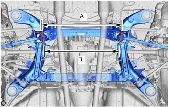
Measure the distance between the centers of the 2 installation bolts of the rear No. 2 suspension arm assembly LH and RH.
Standard Length A 629.5 mm (2.06 ft.) Length B 582.7 mm (1.91 ft.) If the distance is not within the specified range, replace the rear suspension member sub-assembly.
-
Visually inspect the press holes on the installation area of the rear upper No. 2 control arm assembly.
Standard The holes are not deformed. If the holes are deformed, replace the rear suspension member.
-
-
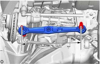
Inspect the lower control arm assembly.
-
Measure the distance between the centers of the 2 installation bolts of the lower control arm assembly.
Standard 357.2 mm (1.17 ft.) If the distance is not within the specified range, replace the lower control arm assembly.
-
-
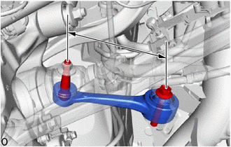
Inspect the rear No. 2 suspension arm assembly.
-
Measure the distance between the centers of the 2 installation bolts of the rear No. 2 suspension arm assembly.
Standard 422.2 mm (1.38 ft.) If the distance is not within the specified range, replace the rear No. 2 suspension arm assembly.
-
-
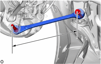
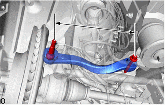
Inspect the rear No. 1 suspension arm assembly.
-
Measure the distance between the center of the rear No. 1 suspension arm assembly installation bolt and the ball joint stud.
Standard 206.0 mm (8.1102 in.) If the distance is not within the specified range, replace the rear No. 1 suspension arm assembly.
-
-
Inspect the rear upper control arm assembly.
-
Measure the distance between the center of the rear upper control arm assembly installation bolt and the ball joint stud.
Standard 324.5 mm (1.06 ft.) If the distance is not within the specified range, replace the rear upper control arm assembly.
-
-
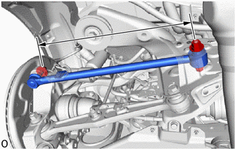
w/o Dynamic Rear Steering:
Inspect the toe control link sub-assembly.
-
Measure the distance between the center of the toe control link sub-assembly installation bolt and the ball joint stud.
Standard 481.0 mm (1.58 ft.) If the distance is not within the specified range, replace the toe control link sub-assembly
-
-
- Click here
REPLACE REAR SUSPENSION ARM ATTACHMENT SUB-ASSEMBLY
-
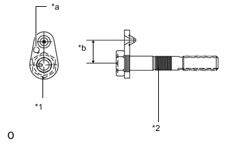
*1 Toe Adjust Plate *2 Rear Suspension Attachment *a Stamping Position *b Dimension A When rear suspension member is not replaced:
-
Use the same stamping No. as the parts that were removed from the left and right side of the vehicle.
-
-
When rear suspension member is replaced:
-
Use stamping A for the parts that were removed from the left and right side of the vehicle.
Part No. information Stamping No. Part No.
Rear Suspension Attachment
Part No.
Toe Adjust Plate
Dimension A A 48709-11020 48452-11010 30 mm (1.1811 in.) B 48709-11030 48452-11020 28 mm (1.1024 in.) C 48709-11040 48452-11030 32 mm (1.2598 in.)
-
-
- Click here
ALIGN FRONT WHEELS FACING STRAIGHT AHEAD
- Click here
PERFORM YAW RATE AND ACCELERATION SENSOR CALIBRATION
- Click here
INSPECT AND ADJUST VEHICLE HEIGHT (w/ Air Suspension)
- Click here
PERFORM INITIALIZATION
Parking support brake system Panoramic view monitor system Parking assist monitor system
- w/o Air Suspension System:
-
Lighting system (EXT)
- Click here
ADJUST HEADLIGHT AIMING
- Click here
CHECK VEHICLE HEIGHT CONTROL
-
Check the vehicle height control operation.
-
After the inspection is completed, return the settings to the recorded values.
-