FRONT DOOR DISASSEMBLY

CAUTION / NOTICE / HINT
The necessary procedures (adjustment, initialization or registration) that must be performed after parts are removed, installed or replaced during the front door disassembly are shown below.
| Replacement Part | Necessary Procedure | Effect/Inoperative Function When Necessary Procedures are not Performed | Link |
|---|---|---|---|
| Removal and installation of auxiliary battery terminal | Memorize steering angle neutral point | LKA/LDA system (for Mono camera type) | for Stereo Camera type: Click here for Mono Camera type: Click here |
| Lane control system (for Stereo camera type) | |||
| Parking support brake system* | |||
| Pre-collision system (for Stereo camera type) | |||
| Pre-collision system (for Mono camera type) | |||
| Adaptive high beam system | |||
Lighting system (EXT) |
|||
| Variable gear ratio steering system | |||
| Parking assist monitor system | |||
| Panoramic view monitor system | |||
| Initialize Rear Door Sunshade System | Rear door sunshade system | ||
| Initialize power trunk lid system | Power trunk lid system | ||
|
Side television camera view adjustment | Panoramic view monitor system | |
|
Initialize power window control system |
|
Click here Click here
Tech Tips
-
Use the same procedure for RHD and LHD vehicles.
-
The procedure listed below is for LHD vehicles.
-
Use the same procedure for the RH and LH sides.
-
The procedure listed below is for the LH side.
-
When removing the front door glass sub-assembly LH, move the front door glass sub-assembly LH to the lowest position before disconnecting the auxiliary battery negative (-) terminal.
PROCEDURE
-
PRECAUTION
CAUTION:
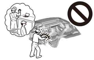
Some of these service operations affect the SRS airbag system. Read the precautionary notices concerning the SRS airbag system before servicing.
Note
After turning the power switch off, waiting time may be required before disconnecting the cable from the negative (-) auxiliary battery terminal. Therefore, make sure to read the disconnecting the cable from the negative (-) auxiliary battery terminal notices before proceeding with work.
-
REMOVE LUGGAGE COMPARTMENT MAT SUB-ASSEMBLY
-
DISCONNECT CABLE FROM NEGATIVE AUXILIARY BATTERY TERMINAL
-
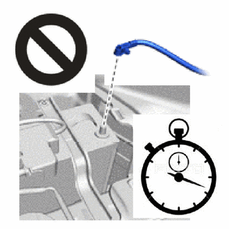
Disconnect the cable from the negative (-) auxiliary battery terminal.
CAUTION:
-
After disconnecting the cable from the negative (-) auxiliary battery terminal, wait for at least 90 seconds to start the operation.
-
If the airbag deploys for any reason, it may cause a serious accident.
Note
When disconnecting the cable, some systems need to be initialized after the cable is reconnected.
-
-
-
REMOVE FRONT DOOR TRIM UPPER COVER LH
-
Detach the claw and remove the front door trim upper cover LH.
-
-
REMOVE FRONT DOOR ARMREST COVER LH
-
Detach the claw and remove the front door armrest cover LH.
-
-
REMOVE FRONT DOOR NO. 2 ARMREST COVER LH
-
Detach the claw and guide and remove the front door No. 2 armrest cover LH.
-
-
REMOVE FRONT DOOR TRIM BOARD SUB-ASSEMBLY LH
-
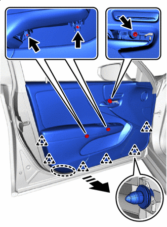

Place Hand Here 
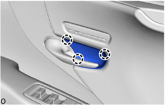
Remove in this Direction Remove the 3 screws.
-
Place your hand at the position shown in the illustration, and while pulling the front door trim board sub-assembly LH toward you, detach the clip and disconnect the front door trim board sub-assembly LH from the front door panel.
-
Remove in this Direction Pull the front door trim board sub-assembly LH in the direction indicated by the arrow shown in the illustration to detach the claw and remove the front door trim board sub-assembly LH.
-
Remove in this Direction Disconnect the front door lock remote control cable assembly LH from the front door inside handle sub-assembly LH.
-
Remove in this Direction 
Push Detach the claw and disconnect the front door inside locking cable assembly LH.
-
Disconnect each connector.
-
-
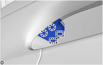
REMOVE MULTIPLEX NETWORK MASTER SWITCH ASSEMBLY (for Driver Side)
-
REMOVE POWER WINDOW REGULATOR SWITCH ASSEMBLY (for Front Passenger Side)
-
REMOVE COURTESY LIGHT ASSEMBLY
-
REMOVE DOOR LOCK CONTROL KNOB BEZEL LH
-
Remove in this Direction Detach the claw and remove the door lock control knob bezel LH together with the front door lock control knob holder LH.
-
-
REMOVE FRONT DOOR LOCK CONTROL KNOB HOLDER LH
-
Detach the claw and remove the front door lock control knob holder LH.
-
-
REMOVE FRONT DOOR INNER TRIM COVER LH
-
Detach the claw and remove the front door inner trim cover LH.
-
-
REMOVE NO. 2 SWITCH BEZEL
-
REMOVE SEAT MEMORY SWITCH LH
-
REMOVE FRONT DOOR INSIDE HANDLE SUB-ASSEMBLY LH
-
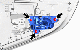
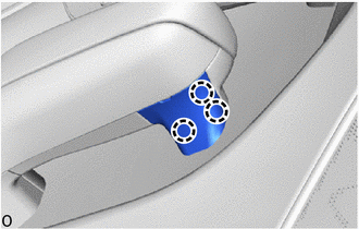
Remove the 3 screws and the front door inside handle sub-assembly LH.
-
-
REMOVE FRONT DOOR TRIM COVER LH
-
Using a clip remover, detach the clip.
-
Remove in this Direction Slide the front door trim cover LH in the direction indicated by the arrow shown in the illustration to detach the clip and remove the front door trim cover LH.
-
Remove the remaining 2 clips on the vehicle side.
-
-
REMOVE UPPER DOOR FRAME GARNISH LH
-
Remove in this Direction Using a clip remover, detach the clip.
-
Detach the guide in the direction indicated by the arrow shown in the illustration and remove the upper door frame garnish LH.
-
-
REMOVE FRONT DOOR GLASS INNER WEATHERSTRIP LH
-
Remove in this Direction Remove the front door glass inner weatherstrip LH in the direction indicated by the arrow as shown in the illustration.
-
-
REMOVE FRONT DOOR VENT SEAL LH
-
Remove in this Direction Remove the front door vent seal LH.
-
-
REMOVE FRONT DOOR PANEL PROTECTOR LH
-
Remove in this Direction Remove the front door panel protector LH.
-
-
REMOVE FRONT NO. 1 SPEAKER ASSEMBLY
-
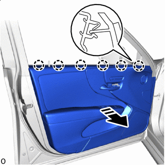
REMOVE FRONT DOOR SERVICE HOLE COVER LH
-
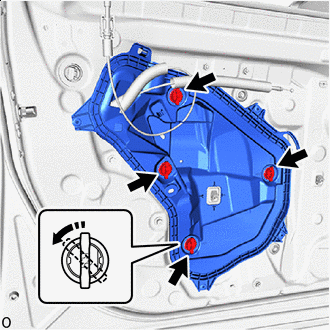
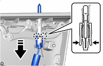
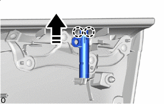
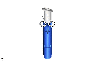
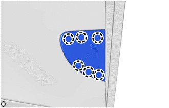
Turn Service Hole Cover Clip Disconnect the wire harness clamps.
-
As shown in the illustration, turn the service hole cover clip 45° to release the lock, and then remove the 4 service hole cover clips.
-
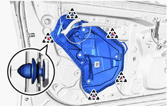
Using a clip remover, detach the clip and remove the front door service hole cover LH.
-
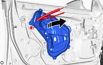
Remove in this Direction Pull out the front door lock remote control cable assembly LH and front door inside locking cable assembly LH from the front door service hole cover LH.
-
-
REMOVE OUTER MIRROR INSTALL HOLE COVER LH
-
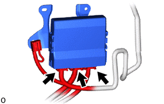
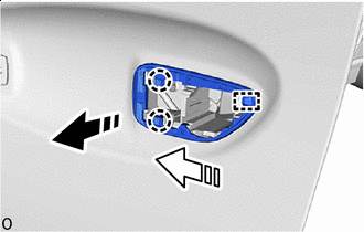
REMOVE FRONT MULTIPLEX NETWORK DOOR ECU LH
-
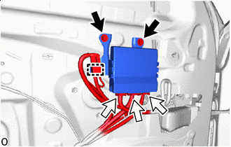
Screw 
Connector Disconnect the clamp and 3 connectors.
-
Remove the 2 screws and front multiplex network door ECU LH.
-
-
REMOVE OUTER REAR VIEW MIRROR ASSEMBLY LH
-
REMOVE DOOR SIDE AIR BAG SENSOR LH
-
REMOVE FRONT DOOR ARMREST SET BRACKET LH
-
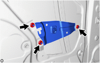
Remove the 3 nuts and front door armrest set bracket LH.
-
Remove the 2 screw grommets.
-
-
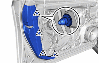
REMOVE FRONT DOOR NO. 3 WEATHERSTRIP LH
-
Using a clip remover, remove the 3 clips.
-

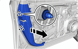
Double-sided Tape Using a clip remover, remove the clip.
-
Remove the double-sided tape and front door No. 3 weatherstrip LH.
-
-
REMOVE FRONT DOOR NO. 2 WEATHERSTRIP LH
-
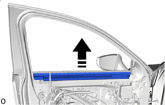
Remove in this Direction Remove the front door No. 2 weatherstrip LH from the front door window frame front moulding LH.
-
-
REMOVE FRONT DOOR BELT MOULDING LH
-
REMOVE FRONT DOOR REAR BELT MOULDING END COVER LH
Tech Tips
When removing the front door rear belt moulding end cover LH, heat the rear door panel and rear front door rear belt moulding end cover LH using a heat light.
Standard Item Temperature Front Door Panel 40 to 60°C (104 to 140°F) Front Door Rear Belt Moulding End Cover LH 20 to 30°C (68 to 86°F) CAUTION:
-
Do not touch the heat light and heated parts.
-
Touching the heat light may result in burns.
-
Touching heated parts for a long time may result in burns.
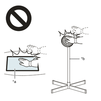
*a Heated Part *b Heat Light
-
Protective Tape Apply protective tape around the front door rear belt moulding end cover LH.
-
Double-sided Tape Using moulding remover D, detach the double-sided tape and clip and remove the front door rear belt moulding end cover LH.
-
-
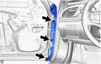
REMOVE FRONT DOOR WINDOW FRAME MOULDING LH(CENTER PILLAR SIDE)
-
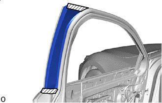
REMOVE FRONT PILLAR UPPER COVER SUB-ASSEMBLY LH
-
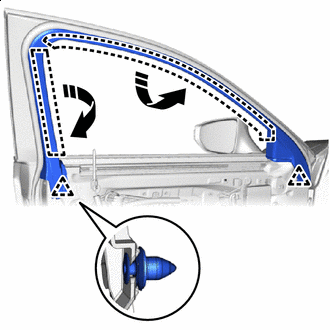
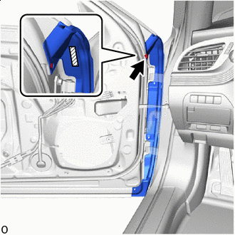
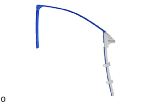
Remove in this Direction(1) 
Remove in this Direction(2) Fold back the front door glass run LH in the direction indicated by the arrow (1) shown in the illustration.
Tech Tips
Do not remove the front door glass run LH from the front pillar upper cover sub-assembly LH.
-
Pull out the front door glass run LH in the direction indicated by the arrow (2) shown in the illustration.
-
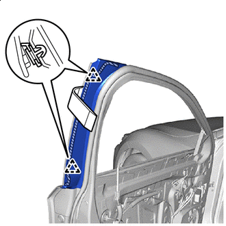
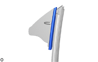
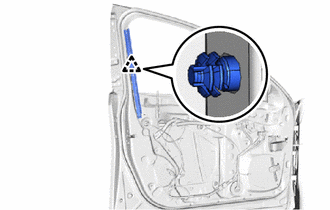
Remove in this Direction(1) Remove in this Direction(2) Remove the 2 bolts, slide the front door glass run LH in the direction indicated by the arrow shown in the illustration and remove it together with the front pillar upper cover sub-assembly LH.
Tech Tips
Be careful not to damage the body and the front door glass sub-assembly LH with the front pillar upper cover sub-assembly LH.
-
-
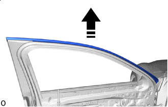
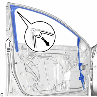
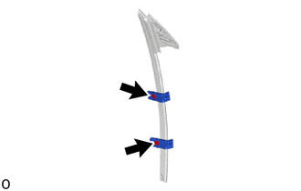
REMOVE FRONT DOOR GLASS RUN LH
-
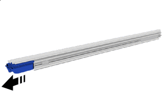
Remove the front door glass run LH.
-
-
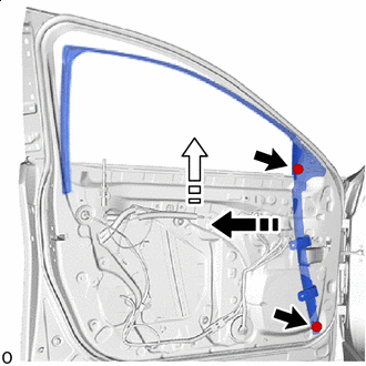
REMOVE FRONT DOOR FRONT GLASS RUN LH
-
Remove the front door front glass run LH.
-
-
REMOVE DOOR GUIDE PROTECTOR
-
Remove the 2 clips and 2 door guide protectors.
-
-
REMOVE FRONT DOOR GLASS SUB-ASSEMBLY LH
-
Connect the 3 front multiplex network door ECU LH connectors.
-
Connect the connector and temporarily install the front door trim board sub-assembly LH.
-
Connect the cable to the negative (-) auxiliary battery terminal.
-
Turn the power switch on (IG).
-
Move the front door glass sub-assembly LH until the installation bolts can be seen.
-
Turn the power switch off.
-
Disconnect the cable from the negative (-) auxiliary battery terminal.
CAUTION:
-
After disconnecting the cable from the negative (-) auxiliary battery terminal, wait for at least 90 seconds to start the operation.
-
If the airbag deploys for any reason, it may cause a serious accident.
-
-
Disconnect the connector and remove the front door trim board sub-assembly LH.
-
Disconnect the 3 front multiplex network door ECU LH connectors.
-
Protective Tape Apply protective tape around the front door panel as shown in the illustration.
-
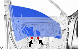
Remove the 2 bolts.
-
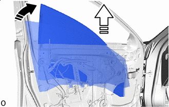
Remove in this Direction(1) Remove in this Direction(2) Remove the front door glass sub-assembly LH in the order shown in the illustration.
Note
Be careful not to damage the front door glass sub-assembly LH.
-
-
REMOVE FRONT DOOR REAR LOWER FRAME SUB-ASSEMBLY LH
-
Remove in this Direction Remove the bolt.
-
Detach the claw and remove the front door rear lower frame sub-assembly LH.
-
-
REMOVE FRONT DOOR NO. 2 GLASS RUN LH
-
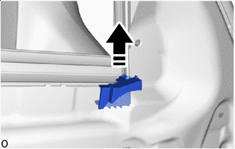
Remove in this Direction Remove the front door No. 2 glass run LH.
-
-
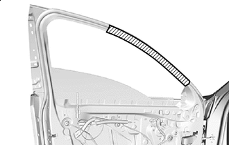
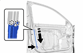
REMOVE FRONT DOOR REAR WINDOW FRAME LH
-
Set a 4.0 mm diameter drill bit into an air drill.
-
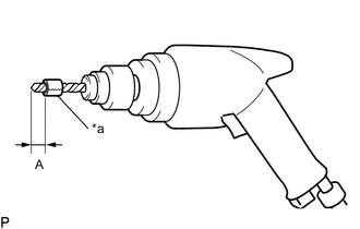
*a Wind Vinyl Tape Wind vinyl tape around the 4.0 mm diameter drill bit 5.0 mm from the tip of the drill.
Standard Value Area Standard Value A 5.0 mm (0.197 in.) Tech Tips
Wind vinyl tape around the drill bit to prevent drilling too deep.
-
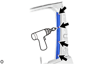
Lightly press the air drill against the rivets, drill off the flanges of the rivets and remove the 4 rivets.
CAUTION:
Be careful of the drilled rivets as they are hot
Note
-
Pressing the air drill excessively will cause the rivet to turn and result in the rivet not being drilled.
-
Do not pry the rivet with the air drill. This may cause damage to the installation hole of the rivet or the drill bit.
-
Wear protective glasses.
-
-
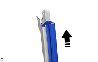
Detach the clip and remove the front door rear window frame LH.
Tech Tips
Do not damage the vehicle body with the front door rear window frame LH.
-
-
REMOVE FRONT DOOR UPPER WINDOW FRAME MOULDING LH
-
REMOVE FRONT DOOR FRONT WINDOW FRAME MOULDING LH
-
REMOVE FRONT DOOR WINDOW REGULATOR ASSEMBLY LH
-
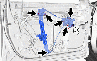
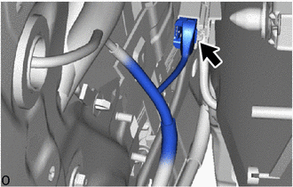
Nut Connector Disconnect the connector.
-
Remove the 6 nuts and the front door window regulator assembly LH.
Note
Do not damage the front door panel assembly with the front door window regulator assembly LH.
Tech Tips
When removing the front door window regulator assembly LH, pull it out from the service hole as shown in the illustration.
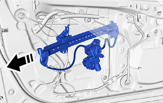
Remove in this Direction
-
-
REMOVE FRONT DOOR OUTSIDE HANDLE ASSEMBLY LH
-
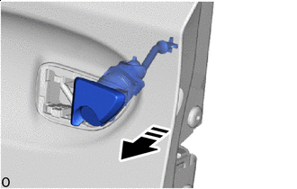
Remove in this Direction Protective Tape Using a thin-bladed screwdriver with its tip wrapped with protective tape, detach the claw and open the connector cover as shown in the illustration.
-
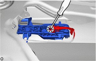
Protective Tape Using a screwdriver with its tip wrapped with protective tape, detach the claw of the connector and disconnect the connector and connector cover as shown in the illustration.
-
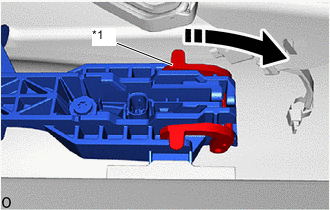
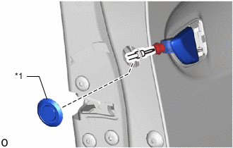
*1 Holder Remove in this Direction Detach the holder as shown in the illustration.
-
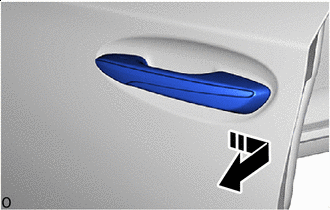
Remove in this Direction Remove the front door outside handle assembly LH in the direction of the arrow shown in the illustration.
-
-
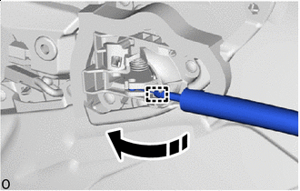
REMOVE FRONT DOOR LOCK CYLINDER ASSEMBLY LH (for Driver Side)
-
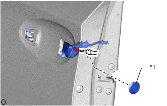
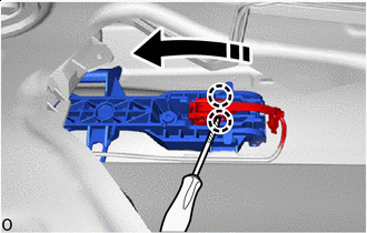
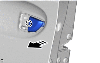
*1 Plug Hole Remove the plug hole.
-
Using a T30 "TORX" socket wrench, loosen the TORX screw.
-
Remove in this Direction Remove the front door lock cylinder assembly LH as shown in the illustration.
-
-
REMOVE FRONT DOOR OUTSIDE HANDLE COVER RH (for Front Passenger Side)
-
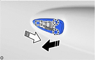
*1 Plug Hole Remove the plug hole.
-
Using a T30 "TORX" socket wrench, loosen the TORX screw.
-
Remove in this Direction Detach the claw and remove the front door outside handle cover RH.
-
-
REMOVE FRONT DOOR FRONT OUTSIDE HANDLE PAD
-
Remove in this Direction(1) Remove in this Direction(2) Detach the claw in the direction indicated by the arrow shown in the illustration.
-
Detach the guide in the direction indicated by the arrow shown in the illustration and remove the front door front outside handle pad.
-
-
REMOVE FRONT DOOR REAR OUTSIDE HANDLE PAD
-
Remove in this Direction(1) Remove in this Direction(2) Detach the claw in the direction indicated by the arrow shown in the illustration.
-
Detach the guide in the direction indicated by the arrow shown in the illustration and remove the front door rear outside handle pad.
-
-
REMOVE FRONT DOOR LOCK OPEN ROD LH
-
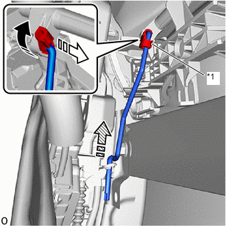
*1 Snap Remove in this Direction(1) Remove in this Direction(2) 
Remove in this Direction(3) Detach the snap as shown in the illustration.
-
Remove the front door lock open rod LH in the direction indicated by the arrow show in the illustration.
-
-
REMOVE FRONT DOOR OUTSIDE HANDLE FRAME SUB-ASSEMBLY LH
-
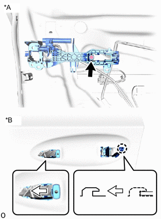
*A Inside *B Outside Using a T30 "TORX" socket wrench, loosen the screw.
-
Detach the claw and remove the front door outside handle frame sub-assembly LH together with the wire harness as shown in the illustration.
-
Disconnect the wire harness clamp and guide and remove the front door outside handle frame sub-assembly LH.
-
-
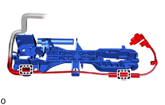
REMOVE FRONT DOOR LOCK WITH MOTOR ASSEMBLY LH
-
REMOVE FRONT DOOR LOCK COVER SUB-ASSEMBLY LH
-
REMOVE FRONT DOOR LOCK REMOTE CONTROL CABLE ASSEMBLY LH
-
REMOVE FRONT DOOR INSIDE LOCKING CABLE ASSEMBLY LH
-
REMOVE FRONT DOOR CHECK ASSEMBLY LH
-
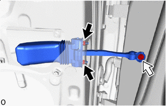
Nut Bolt Remove the bolt, 2 nuts and front door check assembly LH.
-
-
REMOVE FRONT DOOR NO. 4 WEATHERSTRIP LH
-
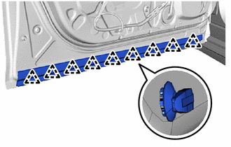
Detach the clip and remove the front door No. 4 weatherstrip LH.
-
-
REMOVE FRONT DOOR PANEL CUSHION
-
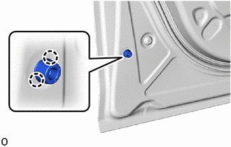
Detach the claw and remove the front door panel cushion.
-
-
REMOVE FRONT DOOR WEATHERSTRIP LH
-
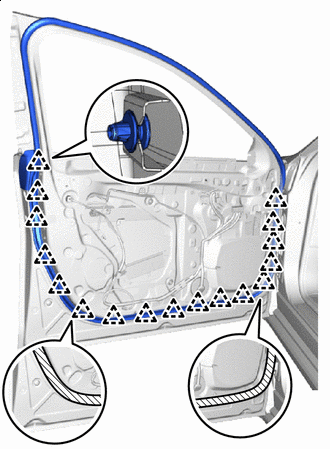
Double-sided Tape Detach the clip.
-
Peel off the double-sided tape shown in the illustration and remove the front door weatherstrip LH.
-