INSTRUMENT PANEL SAFETY PAD INSTALLATION
CAUTION / NOTICE / HINT
Tech Tips
-
Use the same procedure as for the LHD and RHD vehicles.
-
The procedure listed below is for the LHD vehicles.
PROCEDURE
-
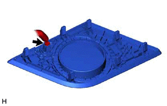
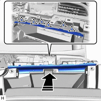
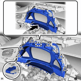
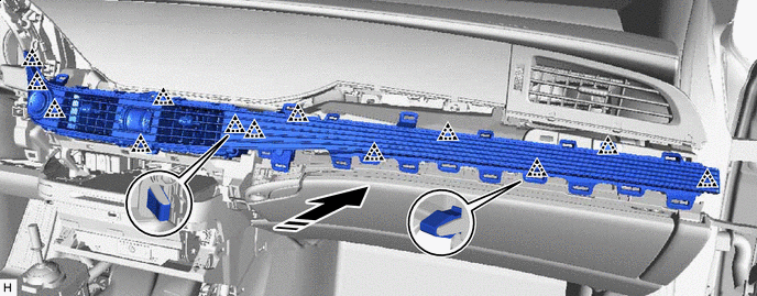
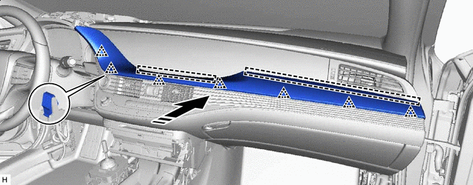
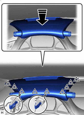
INSTALL INSTRUMENT PANEL SAFETY PAD SUB-ASSEMBLY
-
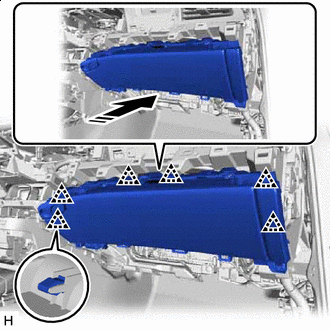
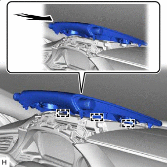
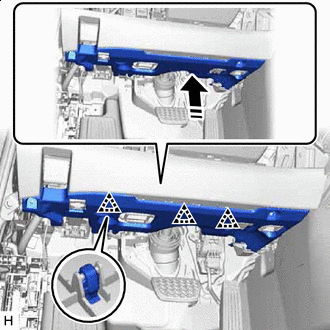
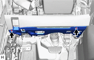
Push in the direction indicated by the arrow shown in the illustration and set the instrument panel safety pad sub-assembly into place on the vehicle.
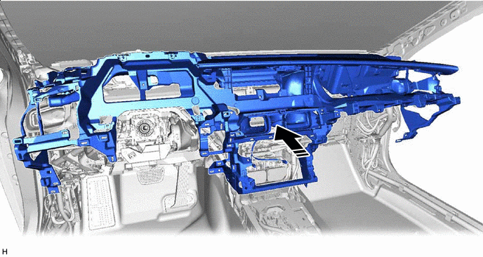

Install in this Direction - - -
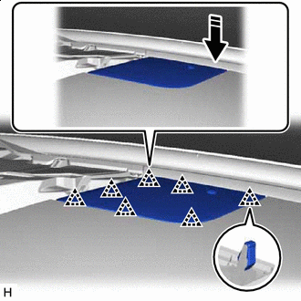
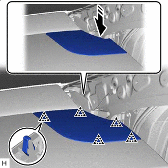
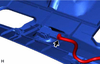
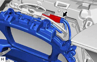
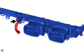
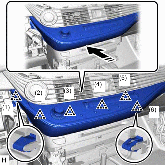
Lift in the direction indicated by the arrow shown in the illustration and insert the guide.
Note
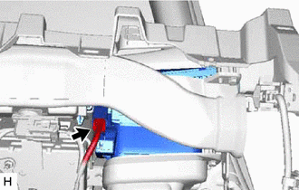
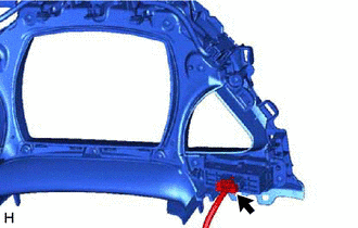
Check the installation condition of the defroster nozzle assembly.
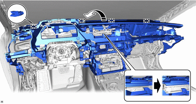
Lift Up Direction 
Defroster nozzle assembly status -
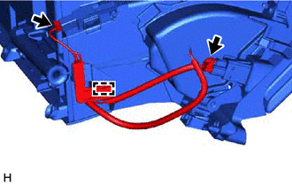
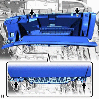
Install the instrument panel safety pad sub-assembly with the nut <F>, 7 bolts <E> and 2 clips <D>.
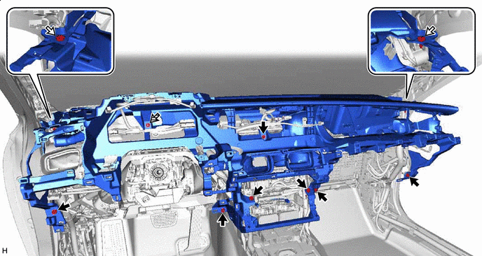
Bolt <E> 
Clip <D> 
Nu <F> - - -
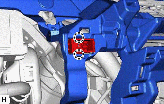
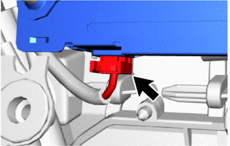
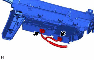
Attach the claw and install the cooler thermistor (room temperature sensor).
-
Connect the connector.
-
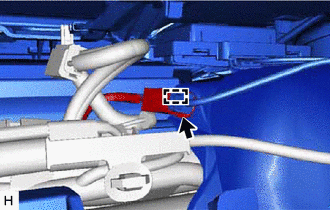
Attach the clamp and connect the connector.
-
Attach the clamp.
-
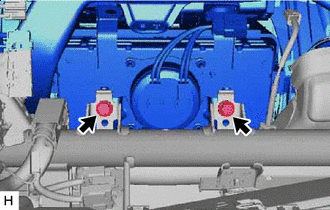
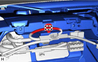
Bolt <C> Install the 2 bolts <C>.
- Torque:
- 20 N*m { 204 kgf*cm, 15 ft.*lbf }
-
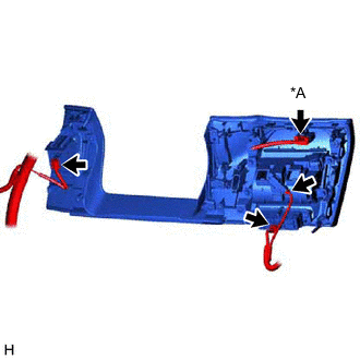
Before connecting the airbag connector, check that the CPA is positioned further back than the housing.
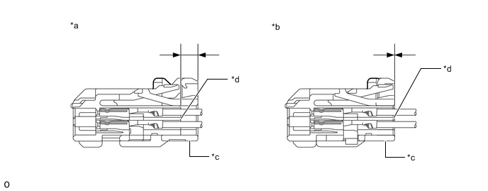
*a CORRECT *b INCORRECT *c CPA *d Housing -
Connect airbag connector:
-
Holding the sides of the CPA, engage it until a locking sound is heard to connect the connector.
Note
-
When connecting the airbag connector, press and connect it straight so as not to twist it.
-
When connecting the connector, do not hold components other than the CPA.
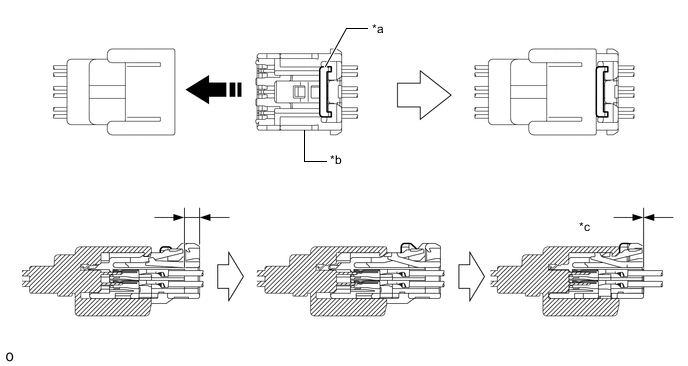
*a Housing Lock *b CPA *c CONNECTED - - Install in this Direction - - -
-
-
-
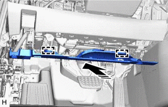
INSTALL TRANSMISSION FLOOR SHIFT ASSEMBLY
-
INSTALL NO. 1 CONSOLE BOX DUCT
-
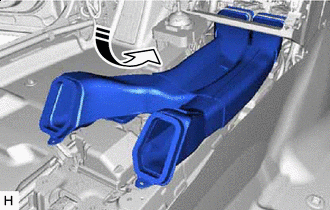
Install in this Direction Insert the No. 1 console box duct in the direction indicated by the arrow shown in the illustration.
-
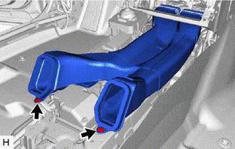
Install the No. 1 console box duct with the 2 clips.
-
-
INSTALL FRONT NO. 3 SPEAKER ASSEMBLY
-
INSTALL NO. 1 INSTRUMENT PANEL SPEAKER PANEL SUB-ASSEMBLY
-
Connect the connector.
-
Install in this Direction Attach the clip and install the No. 1 instrument panel speaker sub-assembly in the direction indicated by the arrow shown in the illustration.
-
-
INSTALL FRONT NO. 2 SPEAKER ASSEMBLY
-
INSTALL NO. 2 INSTRUMENT PANEL SPEAKER PANEL SUB-ASSEMBLY
-
Install in this Direction Attach the clip and install the No. 2 instrument panel speaker panel sub-assembly in the direction indicated by the arrow shown in the illustration.
-
-
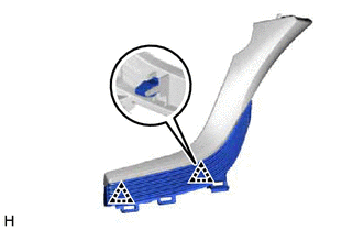
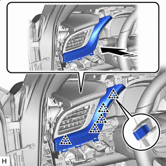
INSTALL FRONT PILLAR GARNISH LH
-
INSTALL FRONT PILLAR GARNISH RH
Tech Tips
Use the same procedure described for the LH side.
-
INSTALL RADIO RECEIVER ASSEMBLY WITH BRACKET
-
INSTALL NO. 2 INSTRUMENT PANEL REGISTER ASSEMBLY
-
Install in this Direction Attach the clip and install the No. 2 instrument panel register assembly in the direction indicated by the arrow shown in the illustration.
-
Connect the connector.
-
-
INSTALL TELEMATICS TRANSCEIVER (w/ Telematics Transceiver)
-
INSTALL GLOVE COMPARTMENT DOOR ASSEMBLY
-
Connect the 2 connectors and attach the clamp.
-
Install in this Direction Attach the clip and install the glove compartment door assembly in the direction indicated by the arrow shown in the illustration.
-
Screw <A> or <B> Install the 2 screws <A> or <B>.
-
Open the glove compartment door assembly.
-
Install the 2 screws <A> or <B>.
-
-
INSTALL GLOVE COMPARTMENT DOOR PAD PLATE
-
Install in this Direction Attach the clip and install glove compartment door pad plate in the direction indicated by the arrow shown in the illustration.
-
Close the glove compartment door assembly.
-
-
INSTALL LOWER NO. 2 INSTRUMENT PANEL AIRBAG ASSEMBLY
-
INSTALL NO. 2 INSTRUMENT PANEL UNDER COVER SUB-ASSEMBLY
-
Connect the connector.
-
Install in this Direction Insert the guide in the direction indicated by the arrow shown in the illustration.
-
Install in this Direction Lift up in the direction indicated by the arrow shown in the illustration to attach the clip and install the No. 2 instrument panel under cover sub-assembly.
-
-
INSTALL MULTI-DISPLAY ASSEMBLY
-
INSTALL COMBINATION METER ASSEMBLY
-
INSTALL INSTRUMENT CLUSTER FINISH PANEL ASSEMBLY
-
Connect the connector.
-
Install in this Direction Attach the clip and install the instrument cluster finish panel assembly in the direction indicated by the arrow shown in the illustration.
-
except Sport Package, w/ Illumination:
-
Connect the connector.
-
-
-
INSTALL STEERING WHEEL SWITCH HOUSING
-
INSTALL INSTRUMENT CLUSTER FINISH PANEL GARNISH ASSEMBLY
-
Connect the connector.
-
Attach the clip and install the instrument cluster finish panel garnish assembly in the direction indicated by the arrow shown in the illustration.
Install in this Direction - -
-
-
INSTALL AIR CONDITIONING CONTROL ASSEMBLY
-
INSTALL LOWER INSTRUMENT PANEL FINISH PANEL ASSEMBLY
-
Connect the 2 connectors.
-
Install in this Direction Attach the clip in the order shown in the illustration.
-
Attach the clip in the order shown in the illustration and remove the lower instrument panel finish panel assembly.
Install in this Direction - -
-
-
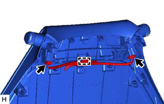
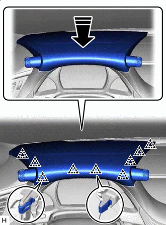
INSTALL INSTRUMENT PANEL SAFETY PAD INSERT SUB-ASSEMBLY
-
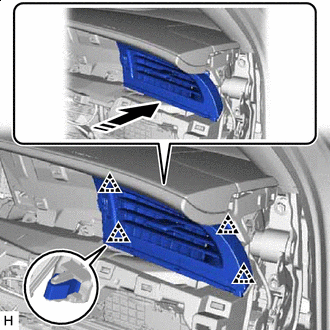
Insert the guide, attach the clip and install the instrument panel safety pad insert sub-assembly in the direction indicated by the arrow shown in the illustration.
Install in this Direction - -
-
-
INSTALL NO. 1 INSTRUMENT PANEL REGISTER ASSEMBLY
-
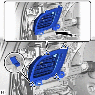
Install in this Direction Attach the clip and install the No. 1 instrument panel register assembly in the direction indicated by the arrow shown in the illustration.
-
Connect the connector.
-
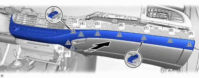
Install in this Direction Attach the clip and install the No. 1 instrument panel safety pad sub-assembly in the direction indicated by the arrow shown in the illustration.
-
Install the screw.
-
-
INSTALL NO. 1 INSTRUMENT CLUSTER MOULDING
-
Attach the clip and install the No. 1 instrument cluster moulding to the No. 1 instrument panel safety pad.
-
-
INSTALL NO. 1 INSTRUMENT PANEL SAFETY PAD
-
Install in this Direction Attach the clip and install the No. 1 instrument panel safety pad together with the No. 1 instrument cluster moulding in the direction indicated by the arrow shown in the illustration.
-
-
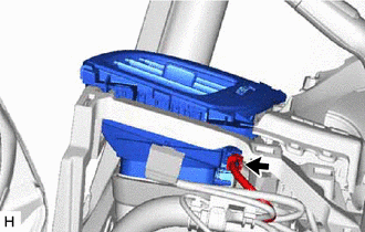
INSTALL NO. 2 INSTRUMENT PANEL SAFETY PAD SUB-ASSEMBLY
-
Connect the 2 connectors and attach the clamp.
-
w/ Headup Display:
-
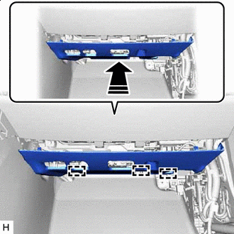
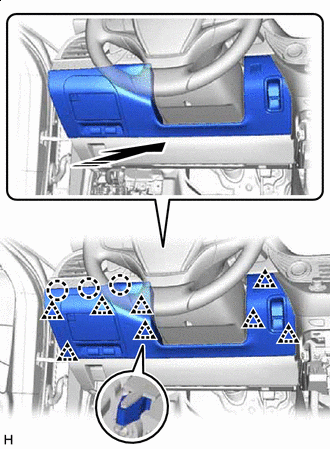
Install in this Direction Align the guide in the direction indicated by the arrow shown in the illustration.
-
Install in this Direction Attach the clip and install the No. 2 instrument panel safety pad sub-assembly in the direction indicated by the arrow shown in the illustration.
-
-
w/o Headup Display:
-

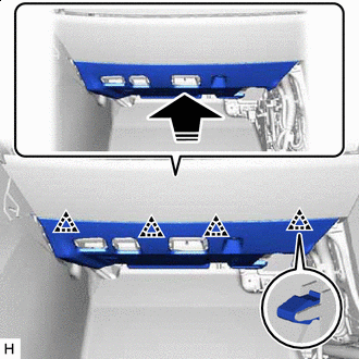
Install in this Direction Align the guide and attach the clip in the direction indicated by the arrow in the illustration.
-
Install in this Direction Attach the clip and install the No. 2 instrument panel safety pad sub-assembly in the direction indicated by the arrow shown in the illustration.
-
-
-
INSTALL LOWER NO. 1 INSTRUMENT PANEL AIRBAG ASSEMBLY
-
INSTALL NO. 1 INSTRUMENT PANEL UNDER COVER SUB-ASSEMBLY
-
Connect the connector.
-
Install in this Direction Insert the guide in the direction indicated by the arrow shown in the illustration.
-
Install in this Direction Lift up in the direction indicated by the arrow shown in the illustration to attach the clip and install the No. 1 instrument panel under cover sub-assembly.
-
Screw <A> or <B> Install the 2 screws <A> or <B>.
-
-
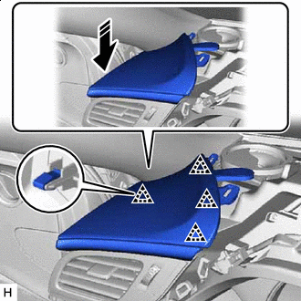
INSTALL LOWER NO. 1 INSTRUMENT PANEL PAD SUB-ASSEMBLY
-
*A w/ Combination Switch w/ Combination Switch:
-
Connect the connector.
-
-
Connect the 3 connectors.
-
Install in this Direction Attach the clip and claw and install the No. 1 lower instrument panel pad sub-assembly in the direction indicated by the arrow shown in the illustration.
-
-
INSTALL INSTRUMENT SIDE PANEL LH
-
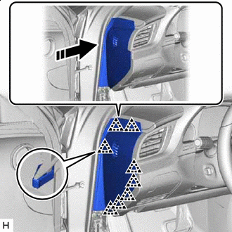
Install in this Direction Attach the clip and install the instrument side panel LH in the direction indicated by the arrow shown in the illustration.
-
-
INSTALL COWL SIDE TRIM BOARD LH
-
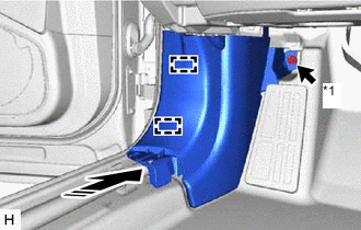
*1 Cap nut Attach the clamp and install the cowl side trim board LH in the direction indicated by the arrow shown in the illustration.
-
Install the cap nut.
-
-
INSTALL FRONT DOOR SCUFF PLATE LH
-
INSTALL INSTRUMENT SIDE PANEL RH
-
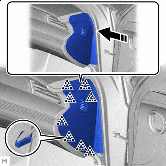
Install in this Direction Attach the clip and install the instrument side panel RH in the direction indicated by the arrow shown in the illustration.
-
-
INSTALL COWL SIDE TRIM BOARD RH
Tech Tips
Use the same procedure described for the LH side.
-
INSTALL FRONT DOOR SCUFF PLATE RH
-
INSTALL CONSOLE BOX ASSEMBLY
-
CONNECT CABLE TO NEGATIVE AUXILIARY BATTERY TERMINAL
Note
When disconnecting the cable, some systems need to be initialized after the cable is reconnected.
-
INSTALL LUGGAGE COMPARTMENT MAT SUB-ASSEMBLY
-
PERFORM DIAGNOSTIC SYSTEM CHECK
-
CHECK SRS WARNING LIGHT
-
PERFORM SYSTEM CALIBRATION