HV BATTERY REMOVAL

CAUTION / NOTICE / HINT
The necessary procedures (adjustment, calibration, initialization, or registration) that must be performed after parts are removed and installed, or replaced during HV battery removal/installation are shown below.
| Replacement Part or Procedure | Necessary Procedure | Effect/Inoperative when not Performed | Link |
|---|---|---|---|
| Disconnect cable from negative auxiliary battery terminal | Memorize steering angle neutral point | LKA/LDA system (for Mono camera type) | for Stereo Camera type: Click here for Mono Camera type: Click here |
| Lane control system (for Stereo camera type) | |||
| Parking support brake system* | |||
| Pre-collision system (for Mono camera type) | |||
| Pre-collision system (for Stereo camera type) | |||
| Adaptive high beam system | |||
Lighting system (EXT) |
|||
| Variable gear ratio steering system | |||
| Parking assist monitor system | |||
| Panoramic view monitor system | |||
| Initialize rear door sunshade system | Rear door sunshade system | ||
| Initialize power trunk lid system | Power trunk lid system | ||
| HV battery |
|
Warning light illumination | |
| DRS ECU (rear steering control ECU) | Perform neutral position memorization and motor rotation angle sensor calibration |
|
|
for LHD:
for RHD: |
Initialize position control ECU | Rear power seat control system |
Click here Click here
CAUTION:
-
Orange wire harnesses and connectors indicate high-voltage circuits. To prevent electric shock, always follow the procedure described in the repair manual.
-

To prevent electric shock, wear insulated gloves when working on wire harnesses and components of the high voltage system.
Tech Tips
When disposing of an HV battery, make sure to return it through an authorized collection agent who is capable of handling it safely. If the HV battery is returned via the manufacturer specified route, it will be returned properly and in a safe manner by an authorized collection agent.
PROCEDURE
-
PRECAUTION
Note
-
After turning the power switch off, waiting time may be required before disconnecting the cable from the negative (-) auxiliary battery terminal. Therefore, make sure to read the disconnecting the cable from the negative (-) auxiliary battery terminal notices before proceeding with work.
-
When the cable is disconnected from the negative (-) auxiliary battery terminal, some systems need to be initialized after the cable is reconnected.
-
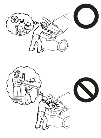
If the HV battery has been struck or dropped, replace it.
-
When connecting a connector to the HV battery, confirm that the connector is securely connected through the following:
- Push the connector until a click sound is heard.
- Visually check and confirm that the connector is securely connected by pulling on it.
-
Make sure to insulate the high-voltage connectors and terminals of the HV battery with insulating tape after removing it.
If the HV battery stored without insulating the connectors and terminals, electric shock or fire may result.
-
When performing repairs around the HV battery, such as using a tap, do not allow metal shavings to enter the HV battery.
-
Do not touch any high voltage wire harnesses, connectors or parts with bare hands.
-
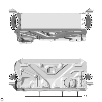
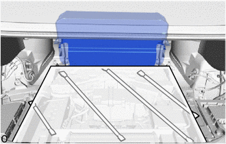
*1 No. 1 HV Battery Carrier Sheet Hold the areas shown in the illustration and lift the HV battery.
-
Do not break the No. 1 HV battery carrier sheet.
-
Do not allow foreign matter, such as grease or oil, to adhere to the bolts or nuts of the HV battery.
-
Do not put your hands into the openings of the HV battery.
-
When removing/installing/moving the HV battery assembly, make sure not to tilt it more than 80°.
-
Do not climb on top of or stand on the HV battery.
-
Do not allow any foreign matter or water to enter the HV battery.
-
If any bolts, nuts or clips are dropped into the HV battery, make sure to remove them.
-
-
READ VALUE USING TECHSTREAM
-
Connect the Techstream to the DLC3.
-
Turn the power switch on (IG).
-
Enter the following menus: Powertrain / HV Battery / Data List / Hybrid Battery Temperature 1 to 6.
Powertrain > HV Battery > Data ListTester Display Hybrid Battery Temperature 1 Hybrid Battery Temperature 2 Hybrid Battery Temperature 3 Hybrid Battery Temperature 4 Hybrid Battery Temperature 5 Hybrid Battery Temperature 6 -
Read the Data List.
Note
If any of the temperatures listed in "Hybrid Battery Temperature 1 to 6" are 50°C or more, leave the vehicle until the temperature drops to less than 50°C.
-
-
REMOVE LUGGAGE COMPARTMENT MAT SUB-ASSEMBLY
-
DISCONNECT CABLE FROM NEGATIVE AUXILIARY BATTERY TERMINAL
Note
When disconnecting the cable, some systems need to be initialized after the cable is reconnected.
-
REMOVE TOOL BOX
-
REMOVE LUGGAGE COMPARTMENT FLOOR MAT
-
REMOVE LUGGAGE COMPARTMENT TRIM COVER RH
-
REMOVE LUGGAGE COMPARTMENT TRIM COVER LH
-
REMOVE SIDE TRIM BOX
-
REMOVE REAR FLOOR FINISH PLATE
-
REMOVE LOWER INNER LUGGAGE COMPARTMENT TRIM COVER
-
REMOVE NO. 1 LUGGAGE COMPARTMENT LIGHT ASSEMBLY
-
REMOVE REAR LUGGAGE COMPARTMENT TRIM COVER
-
REMOVE FRONT LUGGAGE COMPARTMENT TRIM COVER (w/o Rear Air Conditioning System)
-
REMOVE FRONT LUGGAGE COMPARTMENT TRIM COVER (w/ Rear Air Conditioning System)
-
REMOVE LUGGAGE COMPARTMENT TRIM COVER ASSEMBLY RH
-
REMOVE LUGGAGE COMPARTMENT TRIM COVER ASSEMBLY LH
-
REMOVE REAR LUGGAGE COMPARTMENT TRAY BRACKET RH
-
REMOVE REAR LUGGAGE COMPARTMENT TRAY BRACKET LH
Tech Tips
Perform the same procedure as for the RH side.
-
REMOVE SERVICE PLUG GRIP
-
REMOVE INVERTER COVER ASSEMBLY RH (for LHD)
-
REMOVE INVERTER COVER ASSEMBLY LH (for RHD)
-
REMOVE COWL TOP VENTILATOR LOUVER SUB-ASSEMBLY
-
REMOVE CONNECTOR COVER ASSEMBLY
-
CHECK TERMINAL VOLTAGE
-
INSTALL CONNECTOR COVER ASSEMBLY
-
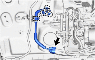
DISCONNECT HV FLOOR UNDER WIRE
-
Detach the claw, clamp and remove the battery terminal connector cover.
-
Remove the nut and disconnect the HV floor under wire.
-
-
REMOVE SUB-BATTERY MODULE ASSEMBLY
-
REMOVE NO. 3 EARTH WIRE
-
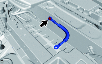
Remove the bolt and No. 3 earth wire.
-
-
REMOVE AUXILIARY BATTERY
-
REMOVE EARTH WIRE
-
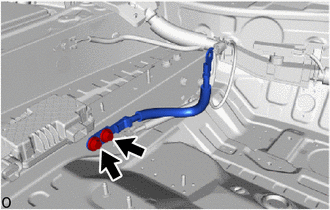
Remove the 2 bolts and earth wire.
-
-
REMOVE BATTERY CARRIER CATCH BRACKET SUB-ASSEMBLY
-
REMOVE BATTERY CARRIER ASSEMBLY
-
REMOVE REAR STEERING CONTROL ECU (w/ Dynamic Rear Steering)
-
REMOVE NO. 1 LUGGAGE ROOM WIRE
-
w/ Air Suspension:
-
Disconnect the connector from the height control compressor.
-
Disengage clamp and 3 claws.
-
-
Disconnect the connectors.
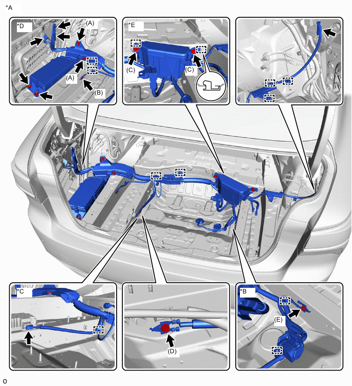
*A w/ Air Suspension *B w/ Dynamic Rear Steering *C w/ 100W Voltage Inverter *D Relay Block A *E Relay Block B - - 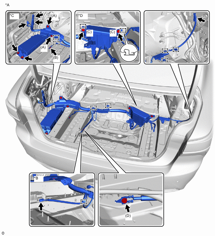
*A w/o Air Suspension *B w/ 100W Voltage Inverter *C Relay Block A *D Relay Block B -
w/ Dynamic Rear Steering:
-
Detach the 2 clamps.
-
Remove the bolt (E).
-
-
w/ 100W Voltage Inverter:
-
Detach the clamp.
-
Disconnect the connector.
-
-
Relay block A:
-
Remove the bolt (A), bolt (B) and 2 nuts.
-
-
Relay block B:
-
Remove the 2 bolts (C).
-
-
Remove the bolt (D).
-
Detach the each clamps and remove the No. 1 luggage room wire.
-
-
REMOVE REAR SEAT CUSHION ASSEMBLY (for Fixed Seat Type)
-
REMOVE REAR SEAT CUSHION LOCK HOOK (for Fixed Seat Type)
-
REMOVE NO. 1 SEAT ARMREST CAP (for Fixed Seat Type)
-
REMOVE REAR SEATBACK ASSEMBLY (for Fixed Seat Type)
-
REMOVE REAR SEAT BACK HOLDER (for Fixed Seat Type)
-
REMOVE REAR SEAT CUSHION ASSEMBLY LH (for Power Seat)
-
REMOVE REAR SEAT CUSHION ASSEMBLY RH (for Power Seat)
-
REMOVE REAR CENTER SEAT CUSHION ASSEMBLY (for Power Seat)
-
REMOVE REAR SEAT CUSHION LOCK HOOK (for Power Seat)
-
REMOVE REAR SEATBACK ASSEMBLY LH (for Power Seat)
-
REMOVE REAR SEATBACK ASSEMBLY RH (for Power Seat)
-
REMOVE REAR CENTER SEAT ARMREST ASSEMBLY (for Power Seat)
-
REMOVE REAR COOLING UNIT ASSEMBLY (w/ Rear Air Conditioning System)
-
REMOVE REAR DOOR SCUFF PLATE LH
-
REMOVE REAR DOOR SCUFF PLATE RH
-
REMOVE REAR SEAT SIDE GARNISH LH
-
REMOVE REAR SEAT SIDE GARNISH RH
-
REMOVE ROOM PARTITION BOARD ASSEMBLY LH (for Power Seat)
-
REMOVE ROOM PARTITION BOARD ASSEMBLY RH (for Power Seat)
-
REMOVE NO. 2 EV BATTERY INTAKE DUCT
-
Remove the 4 clips and No. 2 EV battery intake duct.
-
-
REMOVE NO. 4 HYBRID BATTERY INTAKE DUCT
-
Remove the 4 clips and No. 4 hybrid battery intake duct.
-
-
REMOVE CENTER ROOM PARTITION GARNISH ASSEMBLY (for Power Seat)
-
REMOVE NO. 1 SEAT RECLINING ADJUSTER ASSEMBLY LH (for Power Seat)
-
REMOVE NO. 1 SEAT RECLINING ADJUSTER ASSEMBLY RH (for Power Seat)
-
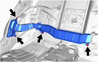
REMOVE CENTER NO. 2 FLOOR TO BRACE EXTENSION
-
Remove the 3 bolts and center No. 2 floor to brace extension.
-
-
DISCONNECT FLOOR WIRE
CAUTION:
Wear insulated gloves.
-
Detach the 2 claws and Remove the connector cover.
-
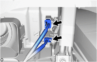
Disconnect the 2 connectors.
-
-
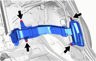
REMOVE CENTER NO. 1 FLOOR TO BLACE EXTENSION
-
Remove the 3 bolts and center No. 1 floor to blace extension.
-
-
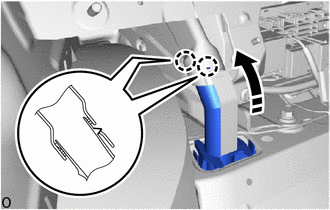
REMOVE NO. 10 HV BATTERY SHIELD PANEL
CAUTION:
Wear insulated gloves.
-
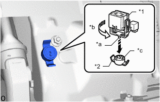
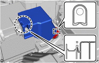
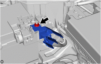
*1 Service Plug Grip *2 Battery Cover Lock Striker *a Projection *b Turn *c Button Using the service plug grip, remove the battery cover lock striker.
Tech Tips
Insert the projection of the service plug grip and turn the button of the battery cover lock striker counterclockwise to release the lock.
-
Remove the 2 nuts and No. 10 HV battery shield panel.
-
-
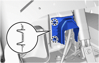
DISCONNECT HV FLOOR UNDER WIRE
CAUTION:
Wear insulated gloves.
-
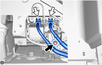
Remove the nut and disconnect the 2 connectors.
-
-
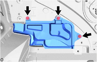
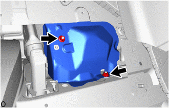
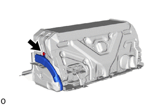
REMOVE NO. 4 HV BATTERY EXHAUST DUCT
CAUTION:
Wear insulated gloves.
-
Detach the 2 claws as shown in the illustration.
-
Remove the No. 4 HV battery exhaust duct.
-
-
REMOVE HV BATTERY ASSEMBLY
CAUTION:
Wear insulated gloves.
-
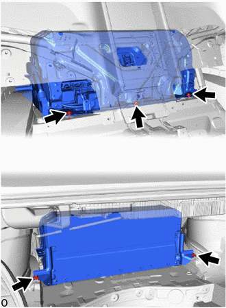
Remove the 3 bolts, 2 nuts and HV battery assembly.
Note
-
Do not allow foreign matter, such as grease or oil, to adhere to the bolts of the HV battery.
-
To prevent the wire harness from being caught, make sure to bundle the wire harness using insulating tape or equivalent.
-
Since the HV battery is very heavy, 2 people are needed to remove it. When removing the HV battery, be careful not to damage the parts around it.
-
When removing the HV battery from the vehicle, do not allow it to contact the vehicle.
-
When removing/installing/moving the HV battery, make sure not to tilt it more than 80°.
-
Insulate the disconnected terminals or connectors with insulating tape.
-
If the HV battery has been struck or dropped, replace it.
Note
Use cardboard or another similar material to protect the HV battery and vehicle body from damage.
-
-
-
REMOVE HV BATTERY DUCT SUB-ASSEMBLY
CAUTION:
Wear insulated gloves.
-
Remove the clip and HV battery duct sub-assembly.
-
-
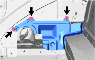
REMOVE NO. 9 HV BATTERY SHIELD PANEL
CAUTION:
Wear insulated gloves.
-
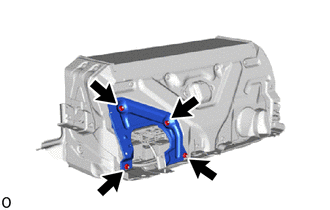
Remove the 4 nuts and No. 9 HV battery shield panel.
-
-
REMOVE HV BATTERY BRACKET LH
CAUTION:
Wear insulated gloves.
-
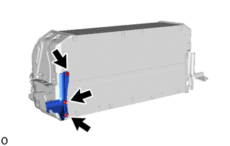
Remove the bolt, 2 nuts and HV battery bracket LH.
-
-
REMOVE HV BATTERY BRACKET RH
Tech Tips
Use the same procedure described for the HV battery bracket LH.
-
PERFORM RECOVERY INSPECTION
-
Before returning the HV battery, make sure to perform a recovery inspection.
-