HV BATTERY STACK REMOVAL
CAUTION / NOTICE / HINT
The necessary procedures (adjustment, calibration, initialization, or registration) that must be performed after parts are removed and installed, or replaced during HV battery stack removal/installation are shown below.
| Replacement Part or Procedure | Necessary Procedure | Effect/Inoperative when not Performed | Link |
|---|---|---|---|
|
Perform current sensor offset learning | DTCs are stored | |
| Hybrid battery terminal block | Perform high voltage fuse accumulated load history reset | DTCs are output | |
|
|
Warning light illumination | |
| Disconnect cable from negative auxiliary battery terminal | Memorize steering angle neutral point | LKA/LDA system (for Mono camera type) | for Stereo Camera type: Click here for Mono Camera type: Click here |
| Lane control system (for Stereo camera type) | |||
| Parking support brake system* | |||
| Pre-collision system (for Mono camera type) | |||
| Pre-collision system (for Stereo camera type) | |||
| Adaptive high beam system | |||
Lighting system (EXT) |
|||
| Variable gear ratio steering system | |||
| Parking assist monitor system | |||
| Panoramic view monitor system | |||
| Initialize rear door sunshade system | Rear door sunshade system | ||
| Initialize power trunk lid system | Power trunk lid system | ||
| HV battery |
|
Warning light illumination | |
| DRS ECU (rear steering control ECU) | Perform neutral position memorization and motor rotation angle sensor calibration |
|
|
for LHD:
for RHD: |
Initialize position control ECU | Rear power seat control system |
Click here Click here
CAUTION:
-
Orange wire harnesses and connectors indicate high-voltage circuits. To prevent electric shock, always follow the procedure described in the repair manual.
-

To prevent electric shock, wear insulated gloves when working on wire harnesses and components of the high voltage system.
-
The hybrid system has high-voltage circuits. Accidents, such as electric shock, or electric leaks may result if the hybrid system is not operated in a correct manner. Make sure to follow the correct procedure.
-
When disposing of an HV battery assembly or hybrid vehicle supply stack sub-assembly, make sure to return them through an authorized collection agent who is capable of handling them safely.
-
Before returning an HV battery assembly, make sure to perform a recovery inspection.
-
Before returning an HV supply stack sub-assembly, make sure to perform a recovery inspection.
-
Make a note of the output DTCs as some of them may be necessary for "Recovery Inspection" of the HV battery assembly and HV supply stack sub-assemblies.
Note
When replacing the No. 1 hybrid vehicle supply stack sub-assembly or No. 2 hybrid vehicle supply stack sub-assembly, it is necessary to check, adjust and equalize the SOC of the HV battery. Otherwise, the engine may run longer than normal, resulting in a decrease in fuel efficiency.
PROCEDURE
-
READ VALUE USING TECHSTREAM
-
Connect the Techstream to the DLC3.
-
Turn the power switch on (IG).
-
Enter the following menus: Powertrain / HV Battery / Data List / Hybrid Battery Temperature 1 to 6.
Powertrain > HV Battery > Data ListTester Display Hybrid Battery Temperature 1 Hybrid Battery Temperature 2 Hybrid Battery Temperature 3 Hybrid Battery Temperature 4 Hybrid Battery Temperature 5 Hybrid Battery Temperature 6 -
Read the Data List.
Note
If any of the temperatures listed in "Hybrid Battery Temperature 1 to 6" are 50°C or more, leave the vehicle until the temperature drops to less than 50°C.
-
-
PRECAUTION
-
REMOVE HV BATTERY ASSEMBLY
-
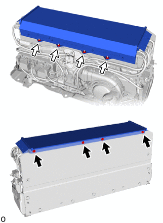
REMOVE UPPER HV BATTERY COVER PANEL
CAUTION:
Be sure to wear insulated gloves and protective goggles.
-
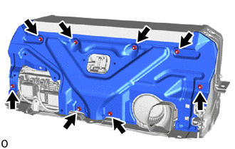
Remove the 8 nuts and upper HV battery cover panel.
-
-
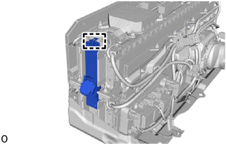
REMOVE NO. 2 HYBRID BATTERY SHIELD SUB-ASSEMBLY
CAUTION:
Be sure to wear insulated gloves and protective goggles.
-
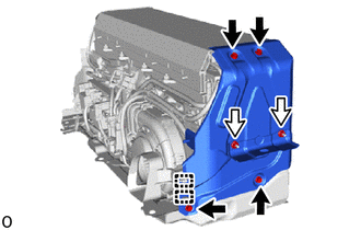
Detach the 2 clamps.
-
Remove the 4 bolts, 2 nuts and No. 2 hybrid battery shield sub-assembly.
-
-
REMOVE NO. 1 HYBRID BATTERY SHIELD SUB-ASSEMBLY
CAUTION:
Be sure to wear insulated gloves and protective goggles.
-
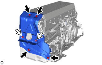
Remove the 4 bolts, 2 nuts and No. 1 hybrid battery shield sub-assembly.
-
-
REMOVE HYBRID BATTERY TERMINAL BLOCK
-
REMOVE UPPER NO. 1 HYBRID BATTERY COVER SUB-ASSEMBLY
CAUTION:
Be sure to wear insulated gloves and protective goggles.
-
Remove the 4 bolts, 4 nuts and upper No. 1 hybrid battery cover sub-assembly.
-
-
REMOVE NO. 1 HYBRID BATTERY EXHAUST DUCT
CAUTION:
Be sure to wear insulated gloves and protective goggles.
-
Detach the guide and remove the No. 1 hybrid battery exhaust duct.
-
-
REMOVE BATTERY VOLTAGE SENSOR (for Upper Side)
-
REMOVE BATTERY ECU ASSEMBLY
-
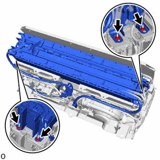
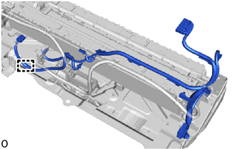
REMOVE NO. 7 HV BATTERY SHIELD SUB-ASSEMBLY (for Upper Side)
CAUTION:
Be sure to wear insulated gloves and protective goggles.
-
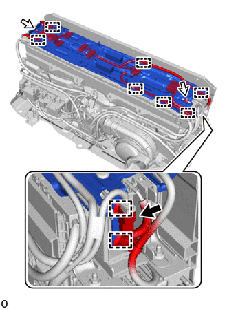
Disconnect the connector.
-
Detach the 9 clamps.
-
Remove the 2 nuts, No. 7 HV battery shield sub-assembly and wire harness clamp bracket.
-
-
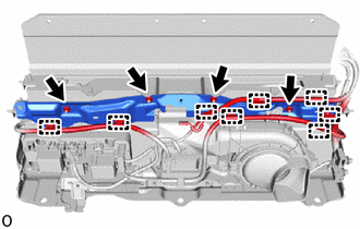
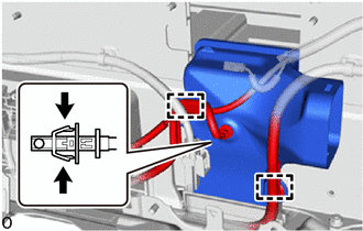
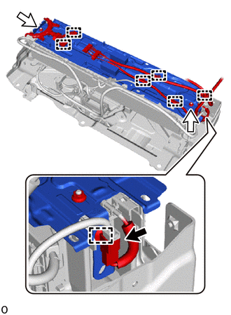
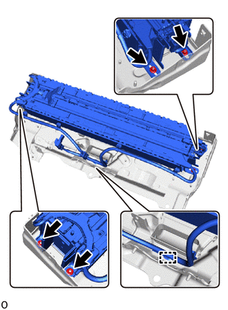
REMOVE NO. 1 HV SUPPLY STACK SUB-ASSEMBLY
CAUTION:
Be sure to wear insulated gloves and protective goggles.
-
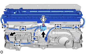
Disconnect the 2 connectors.
Note
Insulate the disconnected connectors with insulating tape.
-
Detach the 6 clamps.
-
Remove the nut.
-
Remove the 4 nuts and No. 1 HV supply stack sub-assembly.
-
-
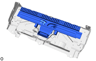
REMOVE NO. 8 HYBRID BATTERY INTAKE DUCT
CAUTION:
Be sure to wear insulated gloves and protective goggles.
-
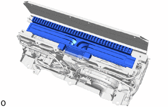
Remove the No. 8 hybrid battery intake duct.
-
-
REMOVE WIRE HARNESS CLAMP BRACKET
CAUTION:
Be sure to wear insulated gloves and protective goggles.
-
Detach the 8 clamps.
-
Remove the 4 nuts and wire harness clamp bracket.
-
-
REMOVE BATTERY COOLING BLOWER ASSEMBLY
CAUTION:
Be sure to wear insulated gloves and protective goggles.
-
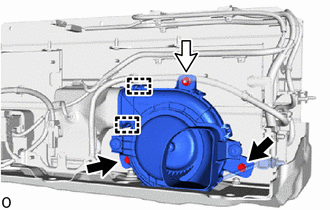
Remove the 2 bolts and nut.
-
Disconnect the 2 fittings on the No. 6 hybrid battery intake duct and remove the battery cooling blower assembly.
-
-
REMOVE NO. 6 HYBRID BATTERY INTAKE DUCT
CAUTION:
Be sure to wear insulated gloves and protective goggles.
-
Detach the 2 clamps.
-
Disconnect the HV battery intake air temperature sensor.
-
Remove the No. 6 hybrid battery intake duct.
-
-
REMOVE HV BATTERY JUNCTION BLOCK ASSEMBLY
CAUTION:
Be sure to wear insulated gloves and protective goggles.
-
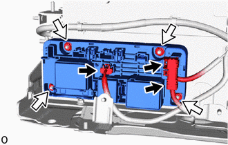
Disconnect the 3 connectors.
Note
Insulate the disconnected connectors with insulating tape.
-
Remove the 4 nuts and HV battery junction block assembly.
Note
-
Do not drop the HV battery junction block assembly, strike it with tools or subject it to impact.
-
If the HV battery junction block assembly is subjected to an impact, replace it with a new one.
-
-
-
REMOVE UPPER HV BATTERY CARRIER SUB-ASSEMBLY
CAUTION:
Be sure to wear insulated gloves and protective goggles.
-
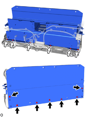
Remove the 7 bolts, 6 nuts and upper HV battery carrier sub-assembly.
-
-
REMOVE BATTERY VOLTAGE SENSOR (for Lower Side)
-
REMOVE NO. 7 HV BATTERY SHIELD SUB-ASSEMBLY (for Lower Side)
CAUTION:
Be sure to wear insulated gloves and protective goggles.
-
Disconnect the connector.
-
Detach the 7 clamps.
-
Remove the 2 nuts, No. 7 HV battery shield sub-assembly and wire harness clamp bracket.
-
-
REMOVE NO. 2 HV BATTERY PACK WIRE
CAUTION:
Be sure to wear insulated gloves and protective goggles.
-
Detach the clamp and remove the No. 2 HV battery pack wire.
-
-
REMOVE NO. 2 HV SUPPLY STACK SUB-ASSEMBLY
CAUTION:
Be sure to wear insulated gloves and protective goggles.
-
Detach the clamp.
-
Remove the 4 nuts and No. 2 HV supply stack sub-assembly.
-
-
REMOVE NO. 9 HYBRID BATTERY INTAKE DUCT
CAUTION:
Be sure to wear insulated gloves and protective goggles.
-
Remove the No. 9 hybrid battery intake duct.
-
-
PERFORM RECOVERY INSPECTION
-
Before returning the HV supply stack sub-assembly, make sure to perform a recovery inspection.
-