PROCEDURE
- Click here
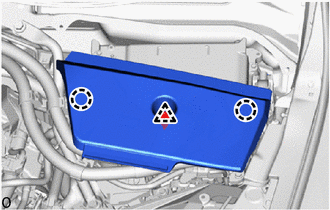
INSTALL HIGH VOLTAGE FUSE
CAUTION:Wear insulated gloves.
Tip:Perform this procedure only when replacement of the high voltage fuse is necessary.
-
Remove the connector cover assembly.
-
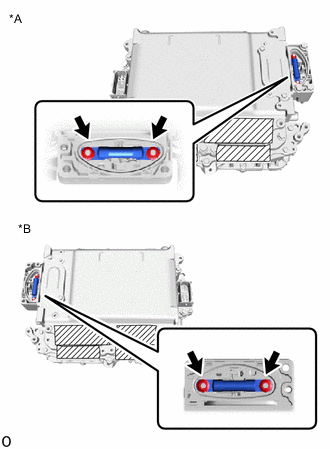
*A for LHD *B for RHD Install the high voltage fuse with the 2 new nuts.
4.0 N*m 41 kgf*cm 35 in.*lbf Note:Be sure to use a torque wrench to tighten the nuts.
-
Temporarily install the connector cover assembly.
-
- Click here
INSTALL NO. 1 INVERTER COOLING HOSE
Tip:Perform this procedure only when replacement of the No. 1 inverter cooling hose is necessary.
-
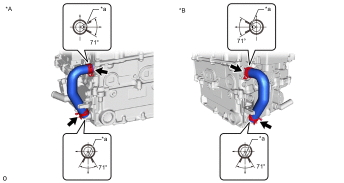
*A for LHD *B for RHD *a Alignment Mark - - Install the No. 1 inverter cooling hose to the inverter with converter assembly and slide the 2 hose clips to secure it.
Note:Do not remove the pieces of cloth or plastic bags from the pipes until installation.
Tip:Make sure that the 2 hose clips are positioned as shown in the illustration.
-
- Click here
INSTALL INVERTER BUS-BAR PLATE SUB-ASSEMBLY
-
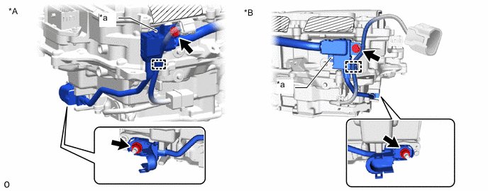
*A for LHD *B for RHD *a Stopper - - Temporarily install the inverter bus-bar plate sub-assembly with the nut by tightening the nut 3 or more revolutions.
Note:If the inverter bus-bar plate sub-assembly is dropped or deformed, replace it with a new one.
Tip:When installing, align with the stopper.
-
Install the bolt and Engage the clamp.
8.0 N*m 82 kgf*cm 71 in.*lbf -
Tighten the nut.
18 N*m 184 kgf*cm 13 ft.*lbf -
Close the terminal cover.
-
- Click here
INSTALL NO. 4 INVERTER BRACKET
-
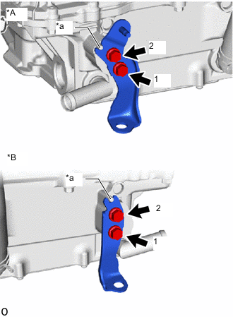
*A for LHD *B for RHD *a Stopper Temporarily install the No. 4 inverter bracket to the inverter with converter assembly with the 2 bolts.
Tip:When installing, align with the stopper.
-
Tighten the 2 bolts in the sequence shown in the illustration.
8.0 N*m 82 kgf*cm 71 in.*lbf
-
- Click here
INSTALL INVERTER WITH CONVERTER ASSEMBLY
CAUTION:Wear insulated gloves.
-
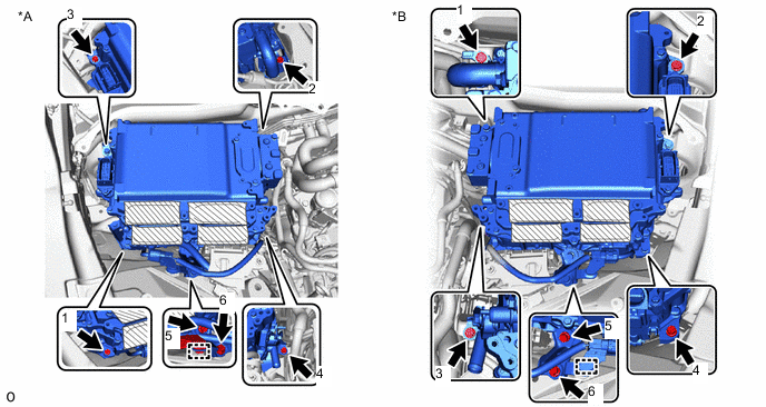
*A for LHD *B for RHD Temporarily install the No. 6 inverter bracket with the 2 bolts.
Note:
-
Since the inverter with converter assembly is very heavy, 2 people are needed to install the inverter with converter assembly. When installing the inverter with converter assembly, do not damage the parts around it.
-
To prevent damage, do not hold the inverter with converter assembly by the connectors.
-
To prevent damage due to static electricity, do not touch the terminals of the disconnected connectors.
-
-
Temporarily install the inverter with converter assembly with the 4 bolts.
-
Tighten the 6 bolts in the order shown in the illustration.
8.0 N*m 82 kgf*cm 71 in.*lbf -
Engage the clamp.
-
*A for LHD *B for RHD Open the inverter bus-bar plate sub-assembly cover.
-
Connect the inverter bus-bar plate sub-assembly with the nut.
8.0 N*m 82 kgf*cm 71 in.*lbf -
Connect the connector.
-
- Click here
INSTALL HV FLOOR UNDER WIRE
CAUTION:Wear insulated gloves.
-
Remove the connector cover assembly.
-
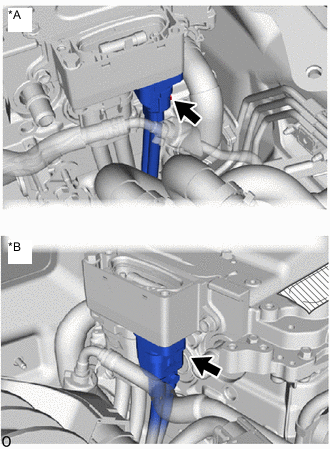
*A for LHD *B for RHD Connect the HV floor under wire.
Note:
-
Do not allow any foreign matter or water to enter the inverter with converter assembly.
-
Do not touch the connector waterproofing rubber or terminals.
-
Do not damage the connectors, connector housings or inverter with converter assembly during connection.
-
Make sure that the connector is fully engaged.
-
-
Secure the HV floor under wire to the inverter with converter assembly with the bolt.
8.0 N*m 82 kgf*cm 71 in.*lbf -
Temporarily install the connector cover assembly.
-
- Click here
INSTALL ENGINE ROOM MAIN WIRE
CAUTION:Wear insulated gloves.
-
Remove the connector cover assembly.
-
*A for LHD *B for RHD Connect the engine room main wire (HV air conditioning wire) to the inverter with converter assembly.
Note:
-
Do not allow any foreign matter or water to enter the inverter with converter assembly.
-
Do not touch the connector waterproofing rubber or terminals.
-
Do not damage the connectors, connector housings or inverter with converter assembly during connection.
-
Make sure that the connector is fully engaged.
-
-
Temporarily install the connector cover assembly.
-
*a Torque Wrench Fulcrum Length for LHD:
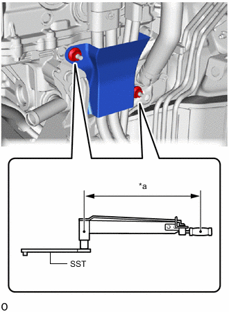
Install the wiring harness clamp bracket.
-
Temporarily install the wiring harness clamp bracket with the 2 nuts.
-
Using SST, tighten the 2 nuts.
09961-00950 Specified tightening torque 8.0 N*m 82 kgf*cm 71 in.*lbf Tip:
-
Calculate the torque wrench reading when changing the fulcrum length of the torque wrench.
-
When using SST (fulcrum length of 150 mm (5.906 in.)) + torque wrench (fulcrum length of 300 mm (11.811 in.)): 5.3 N*m (54 kgf*cm, 47 in.*lbf)
-
-
-
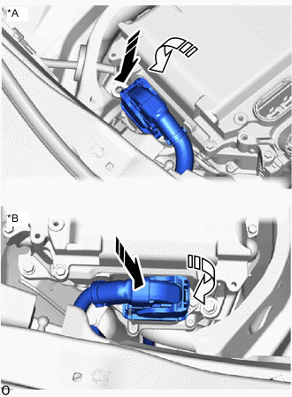
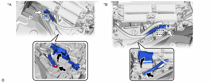
*A for LHD *B for RHD Connect the engine room main wire (inverter with converter assembly connector) to the inverter with converter assembly and lock the connector with the lock lever as shown in the illustration.
-
- Click here
CONNECT NO. 4 INVERTER COOLING HOSE
-
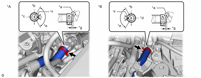
*A for LHD *B for RHD *a Insert *b Upper *c RH Side *d LH Side *e 120° *f Mark (Yellow) *g 2.0 to 7.0 mm (0.079 to 0.276 in.) - - Connect the No. 4 inverter cooling hose to the inverter with converter assembly and slide the hose clip to secure it.
Note:Do not remove the pieces of cloth or plastic bags from the pipe and disconnected hose until installation.
Tip:Make sure that the hose clip is positioned as shown in the illustration.
-
- Click here
CONNECT NO. 5 INVERTER COOLING HOSE
-
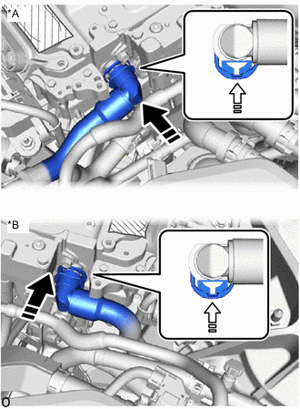
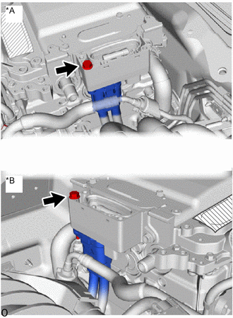
*A for LHD *B for RHD Connect the No. 5 inverter cooling hose to the inverter with converter assembly and lock the hose with the retainer as shown in the illustration.
Note:
-
Push in the retainer until a click sound is heard.
-
Pull on the hose to confirm that the hose is securely connected.
-
If there is foreign matter on the union or the O-ring, clean it with water and finger scouring.
-
To prevent foreign matter from entering the cooling system, do not remove the pieces of cloth or plastic bags from the pipe and disconnected hose until installation.
-
-
- Click here
INSTALL FENDER APRON BRACE SUB-ASSEMBLY RH (for LHD)
-
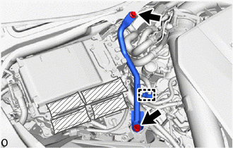
Install the fender apron brace sub-assembly RH with the 2 bolts.
49 N*m 500 kgf*cm 36 ft.*lbf -
Engage the clamp.
-
- Click here
INSTALL FENDER APRON BRACE SUB-ASSEMBLY LH (for RHD)
-
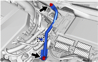
Install the fender apron brace sub-assembly LH with the 2 bolts.
49 N*m 500 kgf*cm 36 ft.*lbf -
Engage the clamp.
-
- Click here
INSTALL INVERTER MOTOR CABLE BRACKET ASSEMBLY
-
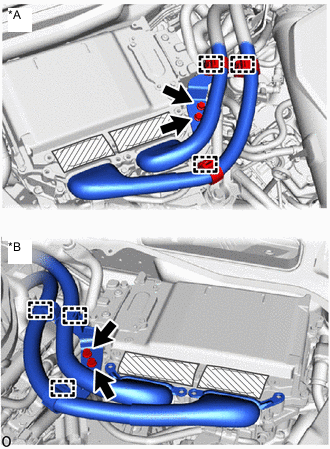
*A for LHD *B for RHD Install the inverter motor cable bracket assembly with the 2 bolts.
8.0 N*m 82 kgf*cm 71 in.*lbf -
Engage the 3 clamps.
-
- Click here
CONNECT MOTOR CABLE
CAUTION:Wear insulated gloves.
-
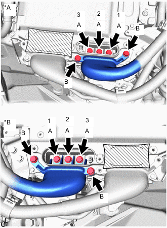
*A for LHD *B for RHD Temporarily install the motor cable to the inverter with converter assembly with the 5 bolts.
Note:
-
Do not allow any foreign matter or water to enter the inverter with converter assembly.
-
Do not touch the connector waterproofing rubber or terminals.
-
Do not damage the terminals, connector housings or inverter with converter assembly when connecting them.
-
-
Using an insulated tool, tighten the 3 bolts (A) in the order shown in the illustration.
8.0 N*m 82 kgf*cm 71 in.*lbf -
Using an insulated tool, tighten the 2 bolts (B).
8.0 N*m 82 kgf*cm 71 in.*lbf
-
- Click here
CONNECT GENERATOR CABLE
CAUTION:Wear insulated gloves.
-
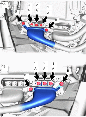
*A for LHD *B for RHD Temporarily install the generator cable to the inverter with converter assembly with the 5 bolts.
Note:
-
Do not allow any foreign matter or water to enter the inverter with converter assembly.
-
Do not touch the connector waterproofing rubber or terminals.
-
Do not damage the terminals, connector housings or inverter with converter assembly when connecting them.
-
-
Using an insulated tool, tighten the 3 bolts (A) in the order shown in the illustration.
8.0 N*m 82 kgf*cm 71 in.*lbf -
Using an insulated tool, tighten the 2 bolts (B).
8.0 N*m 82 kgf*cm 71 in.*lbf
-
- Click here
INSTALL INVERTER TERMINAL COVER
CAUTION:Wear insulated gloves.
-
*A for LHD *B for RHD Temporarily install the inverter terminal cover to the inverter with converter assembly.
Note:
-
Do not touch the inverter terminal cover waterproofing rubber.
-
Do not allow any foreign matter or water to enter the inverter with converter assembly.
-
Make sure that the interlock is fully engaged.
-
-
Press the inverter terminal cover by hand until it is firmly attached to the inverter with converter assembly.
-
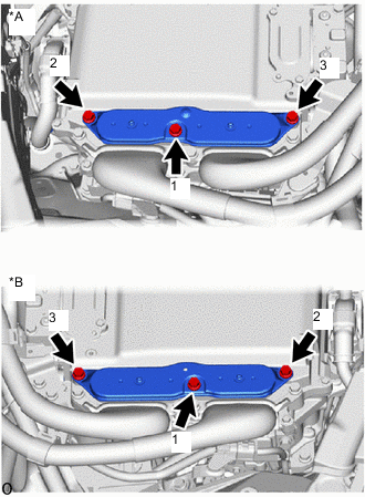
Tighten the 3 bolts to the inverter terminal cover.
8.0 N*m 82 kgf*cm 71 in.*lbf Note:Tighten the 3 bolts in the sequence shown in the illustration.
-
- Click here
INSTALL CONNECTOR COVER ASSEMBLY
CAUTION:Wear insulated gloves.
-
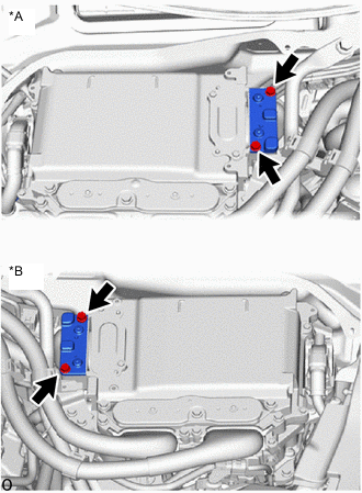
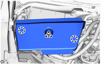
*A for LHD *B for RHD Install the connector cover assembly to the inverter with converter assembly with the 2 bolts.
8.0 N*m 82 kgf*cm 71 in.*lbf Note:
-
Visually confirm that the connector cover assembly waterproofing rubber is securely installed before installing the connector cover assembly.
-
Do not touch the connector cover assembly waterproofing rubber.
-
Make sure that the interlock is fully engaged.
-
-
- Click here
INSTALL COWL TOP VENTILATOR LOUVER SUB-ASSEMBLY
- Click here
INSTALL INVERTER COVER ASSEMBLY RH (for LHD)
-
Engage the clip and 2 claws to install the inverter cover assembly RH.
-
- Click here
INSTALL INVERTER COVER ASSEMBLY LH (for RHD)
-
Engage the clip and 2 claws to install the inverter cover assembly LH.
-
- Click here
INSTALL LOWER RADIATOR AIR DEFLECTOR
- Click here
INSTALL RADIATOR COVER PLATE
- Click here
INSTALL UPPER RADIATOR SUPPORT SEAL
- Click here
INSTALL SERVICE PLUG GRIP
- Click here
CONNECT CABLE TO NEGATIVE AUXILIARY BATTERY TERMINAL
Note:When disconnecting the cable, some systems need to be initialized after the cable is reconnected.
- Click here
INSTALL LUGGAGE COMPARTMENT MAT SUB-ASSEMBLY
- Click here
ADD COOLANT (for Inverter)
- Click here
INSPECT FOR COOLANT LEAK (for Inverter)
- Click here
PERFORM RESOLVER LEARNING