CAUTION / NOTICE / HINT
The necessary procedures (adjustment, calibration, initialization, or registration) that must be performed after parts are removed and installed, or replaced during inverter with converter assembly removal/installation are shown below.
| Replaced Part or Performed Procedure | Necessary Procedures | Effect/Inoperative Function when Necessary Procedure not Performed | Link |
|---|---|---|---|
| Disconnect cable from negative auxiliary battery terminal | Memorize steering angle neutral point | LKA/LDA system (for Mono camera type) | for Stereo Camera type:Click here for Mono Camera type:Click here |
| Lane control system (for Stereo camera type) | |||
| Parking support brake system* | |||
| Pre-collision system (for Stereo camera type) | |||
| Pre-collision system (for Mono camera type) | |||
| Adaptive high beam system | |||
|
|||
| Variable gear ratio steering system | |||
| Parking assist monitor system | |||
| Panoramic view monitor system | |||
| Initialize rear door sunshade system | Rear door sunshade system | ||
| Initialize power trunk lid system | Power trunk lid system | ||
| Inverter with converter assembly | Resolver learning |
|
-
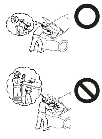
Orange wire harnesses and connectors indicate high-voltage circuits. To prevent electric shock, always follow the procedure described in the repair manual.
-

To prevent electric shock, wear insulated gloves when working on wire harnesses and components of the high voltage system.
PROCEDURE
- Click here
PRECAUTION
Note:After turning the power switch off, waiting time may be required before disconnecting the cable from the negative (-) auxiliary battery terminal. Therefore, make sure to read the disconnecting the cable from the negative (-) auxiliary battery terminal notices before proceeding with work.
- Click here
AIR SUSPENSION CONTROL PROHIBITED (w/ Air Suspension)
- Click here
REMOVE LUGGAGE COMPARTMENT MAT SUB-ASSEMBLY
- Click here
DISCONNECT CABLE FROM NEGATIVE AUXILIARY BATTERY TERMINAL
Note:When disconnecting the cable, some systems need to be initialized after the cable is reconnected.
- Click here
REMOVE SERVICE PLUG GRIP
- Click here
REMOVE UPPER RADIATOR SUPPORT SEAL
- Click here
REMOVE RADIATOR COVER PLATE
- Click here
REMOVE LOWER RADIATOR AIR DEFLECTOR
- Click here
REMOVE INVERTER COVER ASSEMBLY RH (for LHD)
-
Disengage the 2 claws and clip to remove the inverter cover assembly RH.
-
- Click here
REMOVE INVERTER COVER ASSEMBLY LH (for RHD)
-
Disengage the 2 claws and clip to remove the inverter cover assembly LH.
-
- Click here
DRAIN COOLANT (for Inverter)
CAUTION: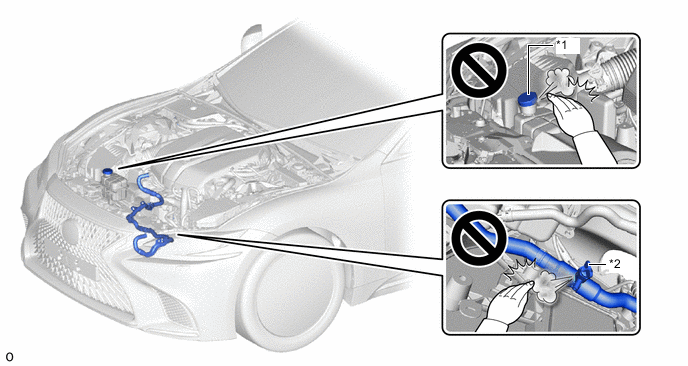
*1 Inverter Reserve Tank Cap *2 Drain Cock Plug
-
To avoid the danger of being burned, do not remove the reserve tank cap or drain cock plug while the coolant (for inverter) is still hot.
-
Pressurized, hot coolant (for inverter) and steam may be released and cause serious burns.
-
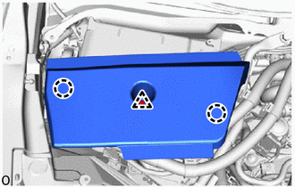
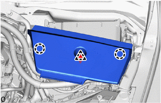
Remove the oil pan protector.
-
for 2WD:
-
for AWD:
-
-
Drain the coolant.
-
- Click here
REMOVE COWL TOP VENTILATOR LOUVER SUB-ASSEMBLY
- Click here
REMOVE CONNECTOR COVER ASSEMBLY
CAUTION:Wear insulated gloves.
-
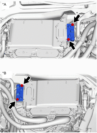
*A for LHD *B for RHD Remove the 2 bolts and connector cover assembly.
Note:
-
Make sure to pull the connector cover assembly straight up, as a connector is connected to the bottom of the cover.
-
Do not touch the connector cover assembly waterproofing rubber.
-
Do not allow any foreign matter or water to enter the inverter with converter assembly.
-
-
- Click here
CHECK TERMINAL VOLTAGE
CAUTION:Wear insulated gloves.
-
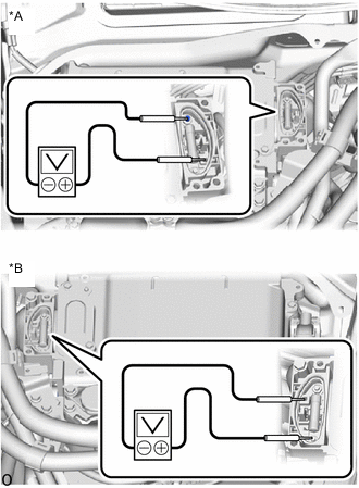
*A for LHD *B for RHD Using a voltmeter, measure the voltage between the terminals of the 2 phase connectors.
Standard Voltage 0 V Note:Do not allow any foreign matter or water to enter the inverter with converter assembly.
Tip:Use a measuring range of DC 750 V or more on the voltmeter.
-
- Click here
TEMPORARILY INSTALL CONNECTOR COVER ASSEMBLY
CAUTION:Wear insulated gloves.
-
*A for LHD *B for RHD Temporarily install the connector cover assembly with the 2 bolts to prevent any foreign matter or water from entering the inverter with converter assembly.
Note:
-
Visually confirm that the connector cover assembly waterproofing rubber is securely installed before installing the connector cover assembly.
-
Do not touch the connector cover assembly waterproofing rubber.
-
Make sure that the interlock is fully engaged.
-
-
- Click here
REMOVE INVERTER TERMINAL COVER
CAUTION:Wear insulated gloves.
-
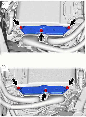
*A for LHD *B for RHD Remove the 3 bolts and inverter terminal cover from the inverter with converter assembly.
Note:
-
Make sure to pull the inverter terminal cover straight up, as a connector is connected to the bottom of the cover.
-
Do not touch the inverter terminal cover waterproofing rubber.
-
Do not allow any foreign matter or water to enter the inverter with converter assembly.
-
-
- Click here
DISCONNECT GENERATOR CABLE
CAUTION:Wear insulated gloves.
-
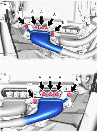
*A for LHD *B for RHD Using an insulated tool, remove the 3 bolts (A).
-
Using an insulated tool, remove the 2 bolts (B), and disconnect the generator cable from the inverter with converter assembly.
Note:
-
Do not allow any foreign matter or water to enter the inverter with converter assembly.
-
Do not touch the connector waterproofing rubber or terminals.
-
Do not damage the terminals, connector housings or inverter with converter assembly during disconnection.
-
Insulate the disconnected terminals with insulating tape.
-
Cover the hole where the cable was connected with tape (non-residue type) or equivalent to prevent entry of foreign matter.
-
-
- Click here
DISCONNECT MOTOR CABLE
CAUTION:Wear insulated gloves.
-
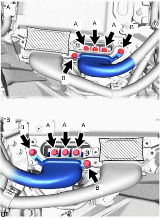
*A for LHD *B for RHD Using an insulated tool, remove the 3 bolts (A).
-
Using an insulated tool, remove the 2 bolts (B), and disconnect the motor cable from the inverter with converter assembly.
Note:
-
Do not allow any foreign matter or water to enter the inverter with converter assembly.
-
Do not touch the connector waterproofing rubber or terminals.
-
Do not damage the terminals, connector housings or inverter with converter assembly during disconnection.
-
Insulate the disconnected terminals with insulating tape.
-
Cover the hole where the cable was connected with tape (non-residue type) or equivalent to prevent entry of foreign matter.
-
-
- Click here
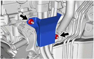
REMOVE INVERTER MOTOR CABLE BRACKET ASSEMBLY
-
*A for LHD *B for RHD Disengage the 3 clamps from the inverter motor cable bracket assembly.
-
Remove the 2 bolts and inverter motor cable bracket from the inverter with converter assembly.
-
- Click here
REMOVE FENDER APRON BRACE SUB-ASSEMBLY RH (for LHD)
-
Disengage the clamp from the fender apron brace sub-assembly RH.
-
Remove the 2 bolts and fender apron brace sub-assembly RH.
-
- Click here
REMOVE FENDER APRON BRACE SUB-ASSEMBLY LH (for RHD)
-
Disengage the clamp from the fender apron brace sub-assembly LH.
-
Remove the 2 bolts and fender apron brace sub-assembly LH.
-
- Click here
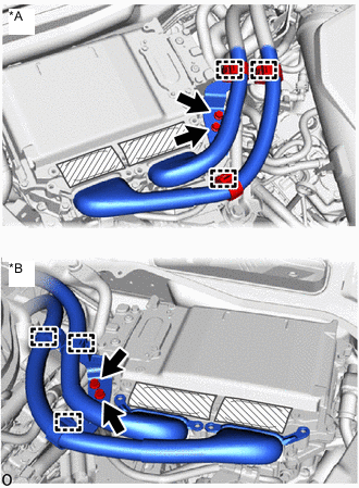
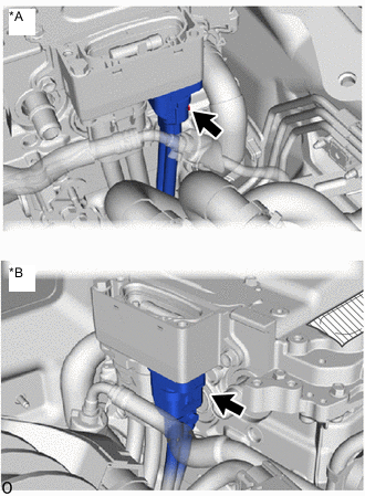
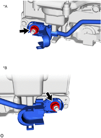
DISCONNECT NO. 5 INVERTER COOLING HOSE
-
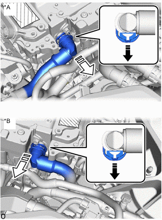
*A for LHD *B for RHD Release the retainer and disconnect the No. 5 inverter cooling hose from the inverter with converter assembly as shown in the illustration.
Note: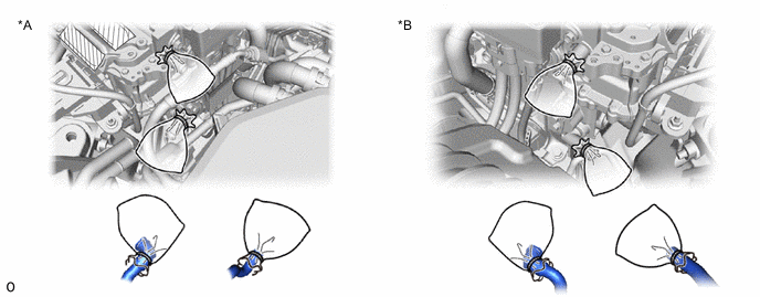
*A for LHD *B for RHD Apply insulating tape to the pipes and in the disconnected hoses, or cover the pipes and hoses with plastic bags to prevent foreign matter from entering the cooling system and to prevent coolant from spilling near the inverter with converter assembly.
-
- Click here
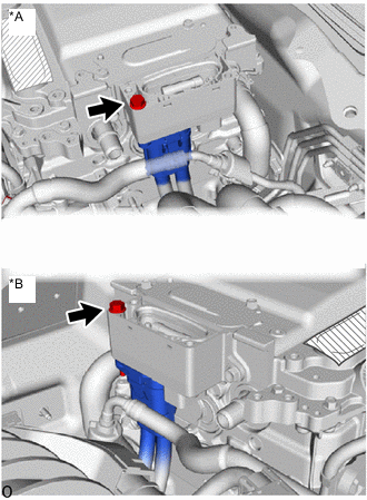
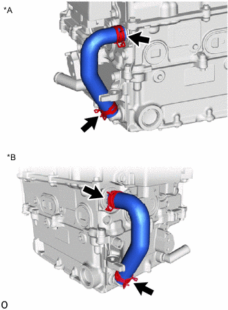
DISCONNECT NO. 4 INVERTER COOLING HOSE
-
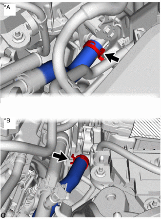
*A for LHD *B for RHD Slide the hose clip and disconnect the No. 4 inverter cooling hose from the inverter with converter assembly.
Note:
*A for LHD *B for RHD Apply insulating tape to the pipes and in the disconnected hoses, or cover the pipes and hoses with plastic bags to prevent foreign matter from entering the cooling system and to prevent coolant from spilling near the inverter with converter assembly.
-
- Click here
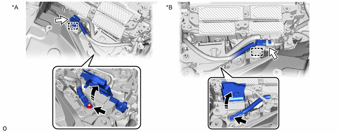
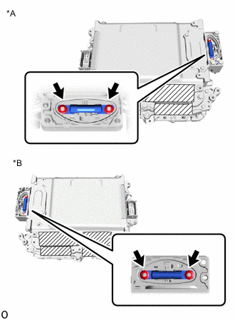
DISCONNECT ENGINE ROOM MAIN WIRE
CAUTION:Wear insulated gloves.
-
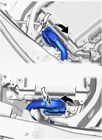
*A for LHD *B for RHD Raise the lock lever and disconnect the engine room main wire (inverter with converter assembly connector) from the inverter with converter assembly as shown in the illustration.
Note:
-
Insulate the disconnected connector with insulating tape.
-
Cover the hole where the connector was connected with tape (non-residue type) or equivalent to prevent entry of foreign matter.
-
-
for LHD:
Remove the 2 nuts and wiring harness clamp bracket.
-
Remove the connector cover assembly.
-
*A for LHD *B for RHD Disconnect the engine room main wire (HV air conditioning wire) from the inverter with converter assembly.
Note:
-
Do not allow any foreign matter or water to enter the inverter with converter assembly.
-
Do not touch the connector waterproofing rubber or terminals.
-
Do not damage the connectors, connector housings or inverter with converter assembly during disconnection.
-
Insulate the disconnected terminals with insulating tape.
-
Cover the hole where the cable was connected with tape (non-residue type) or equivalent to prevent entry of foreign matter.
-
-
Temporarily install the connector cover assembly.
-
- Click here
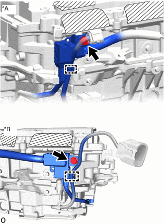
DISCONNECT HV FLOOR UNDER WIRE
CAUTION:Wear insulated gloves.
-
Remove the connector cover assembly.
-
*A for LHD *B for RHD Remove the bolt, and disconnect the HV floor under wire from the inverter with converter assembly.
Note:
-
Do not allow any foreign matter or water to enter the inverter with converter assembly.
-
Do not touch the connector waterproofing rubber or terminals.
-
Do not damage the connectors, connector housings or inverter with converter assembly during disconnection.
-
Insulate the disconnected terminals with insulating tape.
-
Cover the hole where the cable was connected with tape (non-residue type) or equivalent to prevent entry of foreign matter.
-
-
Temporarily install the connector cover assembly.
-
- Click here
REMOVE INVERTER WITH CONVERTER ASSEMBLY
CAUTION:Wear insulated gloves.
-
*A for LHD *B for RHD Open the inverter bus-bar plate sub-assembly cover.
-
Remove the nut and disconnect the inverter bus-bar plate sub-assembly.
-
Disconnect the connector.
-
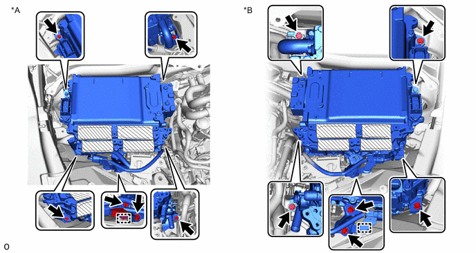
*A for LHD *B for RHD Disengage the clamp from the No. 6 inverter bracket.
-
Remove the 6 bolts, No. 6 inverter bracket and inverter with converter assembly.
Note:
-
Since the inverter with converter assembly is very heavy, 2 people are needed to remove the inverter with converter assembly. When removing the inverter with converter assembly, do not damage the parts around it.
-
To prevent damage, do not hold the inverter with converter assembly by the connectors.
-
To prevent damage due to static electricity, do not touch the terminals of the disconnected connectors.
-
Cover the connectors with insulating tape to prevent foreign matter or water from entering.
Tip:Even after the coolant is drained, coolant remains in the inverter due to its internal structure. Therefore, seal or cover the pipes when removing the inverter so that coolant does not spill out.
-
-
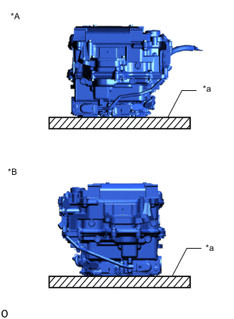
*A for LHD *B for RHD *a Cushion When removing and storing the inverter with converter assembly, make sure to install the inverter terminal cover and place a cushion under the inverter with converter assembly to protect it.
Note:Do not place the inverter with converter assembly upside down.
-
- Click here
REMOVE NO. 4 INVERTER BRACKET
-
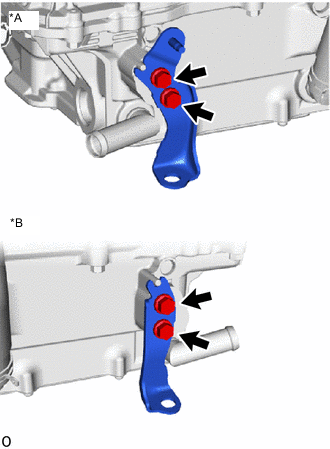
*A for LHD *B for RHD Remove the 2 bolts and No. 4 inverter bracket.
-
- Click here
REMOVE INVERTER BUS-BAR PLATE SUB-ASSEMBLY
-
*A for LHD *B for RHD Disengage the clamp and remove the bolt.
-
Remove the bolt from the inverter bus-bar plate sub-assembly.
-
*A for LHD *B for RHD Open the terminal cover.
-
Remove the nut.
Note:If the stud bolt becomes loose when removing the nut, tighten the stud bolt to a torque of 10 N*m (102 kgf*cm 7 ft.*lbf).
-
Remove the inverter bus-bar plate sub-assembly.
Note:If the inverter bus-bar plate sub-assembly is dropped or deformed, replace it with a new one.
-
- Click here
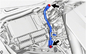
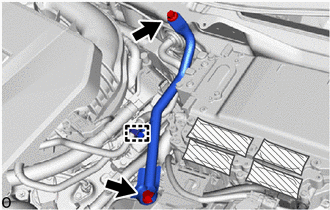
REMOVE NO. 1 INVERTER COOLING HOSE
Tip:Perform this procedure only when replacement of the No. 1 inverter cooling hose is necessary.
-
*A for LHD *B for RHD Slide the 2 hose clips and remove the No. 1 inverter cooling hose from the inverter with converter assembly.
Note:Put pieces of cloth into the pipes or cover the pipes with plastic bags to prevent entry of foreign matter.
-
- Click here
REMOVE HIGH VOLTAGE FUSE
CAUTION:Wear insulated gloves.
Tip:Perform this procedure only when replacement of the high voltage fuse is necessary.
-
Remove the connector cover assembly.
-
*A for LHD *B for RHD Remove the 2 nuts and high voltage fuse.
Note:Do not allow any foreign matter or water to enter the inverter with converter assembly.
-
Temporarily install the connector cover assembly.
-