FRONT AXLE HUB(for AWD) INSTALLATION

CAUTION / NOTICE / HINT
Tech Tips
-
The following procedure is for the LH side.
-
Other than areas where instructions are provided, use the same procedure for the LH and RH sides.
PROCEDURE
-
INSTALL DISC BRAKE AIR GUIDE PLATE
-
Install disc brake air guide plate to the steering knuckle LH.
-
-
INSTALL FRONT AXLE HUB SUB-ASSEMBLY LH
-
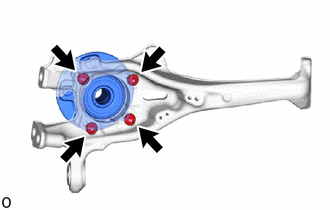
Using a hexagon socket wrench 12 mm, install the front axle hub sub-assembly LH with the 4 bolts.
- Torque:
- 80 N*m { 816 kgf*cm, 59 ft.*lbf }
-
-
TEMPORARILY INSTALL STEERING KNUCKLE LH
-
CONNECT FRONT SUSPENSION UPPER ARM ASSEMBLY
-
TIGHTEN STEERING KNUCKLE LH
-
CONNECT TIE ROD ASSEMBLY LH
-
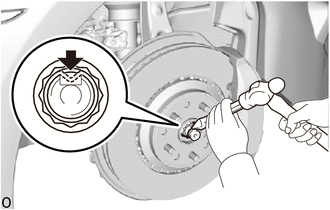
INSTALL FRONT AXLE SHAFT NUT LH
-
Clean the threaded parts on the drive shaft and axle shaft nut using a non-residue solvent.
Note
-
Be sure to perform this work for a new drive shaft.
-
Keep the threaded parts free of oil and foreign objects.
-
-
Using a 30 mm socket wrench, install a new axle shaft nut.
- Torque:
- 294 N*m { 2998 kgf*cm, 217 ft.*lbf }
Note
Do not stake the shaft nut.
Tech Tips
Stake the shaft nut after the axle hub bearing looseness and axle hub runout inspections.
-
-
INSTALL FRONT DISC BRAKE DUST COVER LH
-
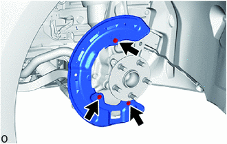
Install the front disc brake dust cover LH with the 3 bolts.
- Torque:
- 8.0 N*m { 82 kgf*cm, 71 in.*lbf }
-
-
INSPECT FRONT AXLE HUB BEARING LOOSENESS
-
INSPECT FRONT AXLE HUB RUNOUT
-
STAKE FRONT AXLE SHAFT NUT LH
-
Using a chisel and hammer, stake the front axle shaft nut.
-
-
INSTALL FRONT DISC LH
-
for 6-Pot Caliper
-
except 6-Pot Caliper
-
-
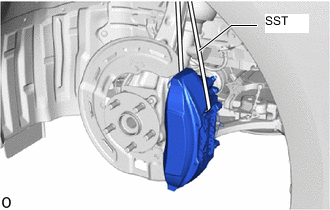
CONNECT DISC BRAKE CYLINDER ASSEMBLY
-
Temporarily install the 5 hub nuts to the front axle hub LH to secure the front disc LH.
Note
Do not apply excessive force to the flexible hose.
-
Temporarily install the disc brake cylinder assembly LH with the bolt on the lower side of the disc brake cylinder assembly LH.
-
Remove the SST.
-
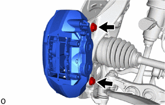
Install the disc brake cylinder assembly LH with the 2 bolts.
- Torque:
- 135 N*m { 1377 kgf*cm, 100 ft.*lbf }
-
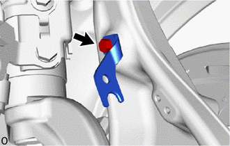
Install the front flexible hose bracket LH to the steering knuckle with the bolt.
- Torque:
- 21 N*m { 214 kgf*cm, 15 ft.*lbf }
-
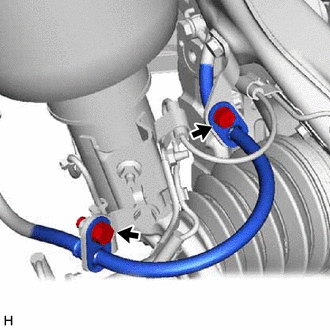
Connect the flexible hose to the front flexible hose with the 2 bolts.
- Torque:
- 20 N*m { 204 kgf*cm, 15 ft.*lbf }
-
for RH side:
for 6-Pot Caliper:
-
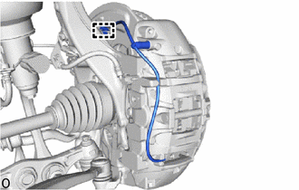
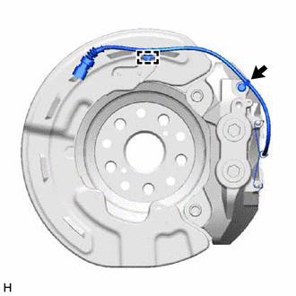
Attach the guide to connect the pad wear indicator wire assembly.
-
Connect the pad wear indicator wire assembly.
-
-
for RH side:
except 6-Poy Caliper:
-
Attach the guide to connect the pad wear indicator wire assembly.
-
Connect the pad wear indicator wire assembly.
-
-
-
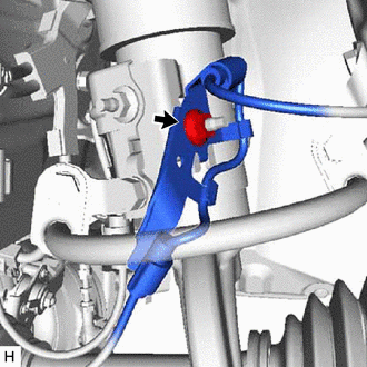
CONNECT FRONT SPEED SENSOR
-
for LH Side:
-
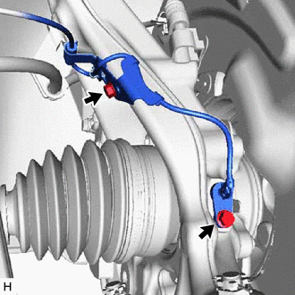
Install the sensor clamp with the bolt.
- Torque:
- 10 N*m { 102 kgf*cm, 7 ft.*lbf }
Note
Do not twist the skid control sensor wire when installing it.
-
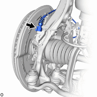
Install the speed sensor with the bolt.
- Torque:
- 8.5 N*m { 87 kgf*cm, 75 in.*lbf }
Note
-
Prevent foreign matter from attaching to the front speed sensor tip.
-
Firmly insert the front speed sensor body into the steering knuckle before tightening the bolt.
-
-
for RH Side:
-
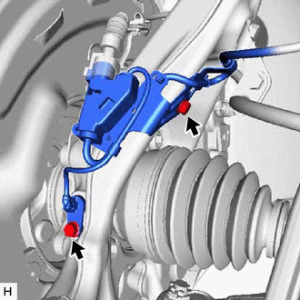
Install the sensor clamp with the bolt.
- Torque:
- 10 N*m { 102 kgf*cm, 7 ft.*lbf }
Note
Do not twist the skid control sensor wire when installing it.
-
Install the speed sensor with the bolt.
- Torque:
- 8.5 N*m { 87 kgf*cm, 75 in.*lbf }
Note
-
Prevent foreign matter from attaching to the front speed sensor tip.
-
Firmly insert the front speed sensor body into the steering knuckle before tightening the bolt.
-
Connect the pad wear indicator connector.
-
-
Install the sensor clamp with the nut.
- Torque:
- 8.5 N*m { 87 kgf*cm, 75 in.*lbf }
Note
Do not twist the skid control sensor wire when installing it.
-
-
STABILIZE SUSPENSION
-
INSTALL STRUT BAR BRACKET SUPPORT SUB-ASSEMBLY (for AWD)
-
INSTALL NO. 2 ENGINE UNDER COVER ASSEMBLY (for AWD)
-
INSTALL NO. 1 ENGINE UNDER COVER ASSEMBLY (for AWD)
-
INSTALL FRONT WHEEL
-
CONNECT BRAKE BOOSTER PUMP CONNECTOR
-
CHECK FOR SPEED SENSOR SIGNAL
-
INSPECT AND ADJUST FRONT WHEEL ALIGNMENT
-
INSPECT AND ADJUST VEHICLE HEIGHT (w/ Air Suspension)
-
PERFORM INITIALIZATION
Parking support brake system Panoramic view monitor system Parking assist monitor system
-
Lighting system (EXT)
w/o Air Suspension System:
-
-
ADJUST HEADLIGHT AIMING