OIL PUMP REMOVAL
CAUTION / NOTICE / HINT
CAUTION:
Do not turn the power switch on (READY) until the oil pump assembly with motor installation is completed.
The necessary procedures (adjustment, calibration, initialization or registration) that must be performed after parts are removed and installed, or replaced during oil pump assembly with motor removal/installation are shown below.
Note
After turning the power switch off, waiting time may be required before disconnecting the cable from the negative (-) auxiliary battery terminal. Therefore, make sure to read the disconnecting the cable from the negative (-) auxiliary battery terminal notices before proceeding with work.
| Replaced Part or Performed Procedure | Necessary Procedure | Effect/Inoperative Function when Necessary Procedure not Performed | Link |
|---|---|---|---|
| Auxiliary battery terminal is disconnected/reconnected | Memorize steering angle neutral point | LKA/LDA system (for Mono camera type) | for Stereo Camera type: Click here for Mono Camera type: Click here |
| Lane control system (for Stereo camera type) | |||
| Parking support brake system*1 | |||
| Pre-collision system (for Stereo camera type) | |||
| Pre-collision system (for Mono camera type) | |||
| Adaptive high beam system | |||
Lighting system (EXT) |
|||
| Variable gear ratio steering system | |||
| Parking assist monitor system | |||
| Panoramic view monitor system | |||
| Initialize rear door sunshade system | Rear door sunshade system | ||
| Initialize power trunk lid system | Power trunk lid system |
Click here Click here
Note
After the power switch is turned off, the navigation system requires approximately a minute to record various types of memory and settings. As a result, after turning the power switch off, wait a minute or more before disconnecting the cable from the negative (-) auxiliary battery terminal.
| System Name | See Procedure |
|---|---|
| Vehicle enrolled in telematics system (w/ Telematics Transceiver for G-BOOK) | 6 minutes |
| Vehicle not enrolled in telematics system (w/ Telematics Transceiver for G-BOOK) | 1 minute |
PROCEDURE
-
DISCONNECT CABLE FROM NEGATIVE AUXILIARY BATTERY TERMINAL
-
REMOVE V-BANK COVER SUB-ASSEMBLY
-
REMOVE RADIATOR COVER PLATE
-
REMOVE LOWER RADIATOR AIR DEFLECTOR
-
REMOVE RADIATOR SUPPORT TO CROSS MEMBER BRACE SUB-ASSEMBLY RH
-
REMOVE NO. 1 AIR CLEANER INLET
-
REMOVE AIR CLEANER ASSEMBLY
-
REMOVE TRANSMISSION UNDER COVER
-
REMOVE NO. 2 ENGINE UNDER COVER ASSEMBLY
-
DRAIN TRANSMISSION FLUID
-
REMOVE NO. 1 EXHAUST PIPE SUPPORT BRACKET SUB-ASSEMBLY
-
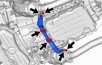
Remove the 2 bolts and 2 nuts, disconnect the No. 1 exhaust pipe support bracket sub-assembly from the exhaust manifold assembly LH and exhaust manifold assembly RH.
-
Remove the 2 bolts and No. 1 exhaust pipe support bracket sub-assembly.
-
-
REMOVE TRANSMISSION OIL PUMP INSULATOR
-
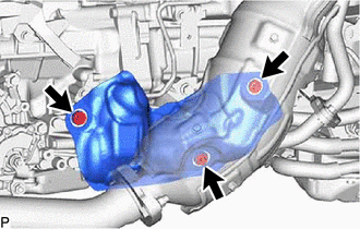
Remove the 3 bolts and transmission oil pump insulator.
-
-
REMOVE TRANSMISSION OIL PUMP INSULATOR BRACKET
-
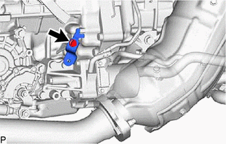
Remove the bolt and transmission oil pump insulator bracket.
-
-
DISCONNECT CONNECTOR
-
DISCONNECT WIRE HARNESS
-
Disconnect the oil pump thermistor connector.
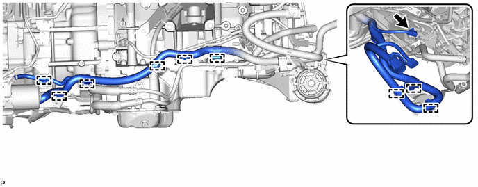
-
Disconnect the 9 wire harness clamps.
-
-
REMOVE OIL WITH MOTOR PUMP ASSEMBLY
-
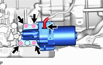
Disconnect the transmission breather hose from the oil with motor pump assembly.
-
Remove the 4 bolts, gasket and oil with motor pump assembly from the hybrid vehicle transmission assembly.
-