MOTOR CABLE REMOVAL
CAUTION / NOTICE / HINT
The necessary procedures (adjustment, calibration, initialization, or registration) that must be performed after parts are removed and installed, or replaced during the motor cable removal/installation are shown below.
Note
After turning the power switch off, waiting time may be required before disconnecting the cable from the negative (-) auxiliary battery terminal. Therefore, make sure to read the disconnecting the cable from the negative (-) auxiliary battery terminal notices before proceeding with work.
| Replaced Part or Performed Procedure | Necessary Procedure | Effect/Inoperative Function when Necessary Procedure not Performed | Link |
|---|---|---|---|
| Auxiliary battery terminal is disconnected/reconnected | Memorize steering angle neutral point | LKA/LDA system (for Mono camera type) | for Stereo Camera type: Click here for Mono Camera type: Click here |
| Lane control system (for Stereo camera type) | |||
| Parking support brake system*1 | |||
| Pre-collision system (for Stereo camera type) | |||
| Pre-collision system (for Mono camera type) | |||
| Adaptive high beam system | |||
Lighting system (EXT) |
|||
| Variable gear ratio steering system | |||
| Parking assist monitor system | |||
| Panoramic view monitor system | |||
| Initialize rear door sunshade system | Rear door sunshade system | ||
| Initialize power trunk lid system | Power trunk lid system | ||
| ECM | Vehicle Identification Number (VIN) registration | DTC P063051 is output | w/ Canister Pump Module: Click here w/o Canister Pump Module: Click here |
|
Inspection after repair |
|
w/ Canister Pump Module: Click here w/o Canister Pump Module: Click here |
| Engine assembly | Inspection after repair | ||
| Drive learning*2 |
|
||
| Parts between the steering wheel and tires have been removed/installed, replaced or adjusted | Perform actuator angle neutral point calibration and initialization |
|
|
| Suspension, tires, etc |
|
Parking support brake system | |
|
Panoramic view monitor system | ||
| Rear television camera assembly optical axis (Back camera position setting) | Parking assist monitor system | ||
| Hybrid vehicle transmission assembly |
|
|
|
|
|
||
| Front bumper assembly (Including removal and installation) |
|
Parking support brake system | |
| Front television camera view adjustment | Panoramic view monitor system |
Click here Click here
*2: After performing the confirmation driving pattern, if the shock during acceleration is large after calibrating the "A/T Code Reset", perform driving learning.
*3: If it is necessary to replace the hybrid vehicle transmission assembly, make sure to perform resolver initialization before starting work.
CAUTION:
-
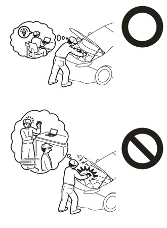
This vehicle has contains high voltage circuits standardized with orange colored wiring and connectors, so follow the instructions in this manual to perform the procedures correctly.
-
If the correct procedures are not followed according to the instructions in this manual, there is a danger of electric shock from the high voltage circuits.
-

Be sure to wear insulating gloves when working on high voltage wiring or components.
-
If work is performed without wearing insulating gloves, there is a danger of electric shock.
-
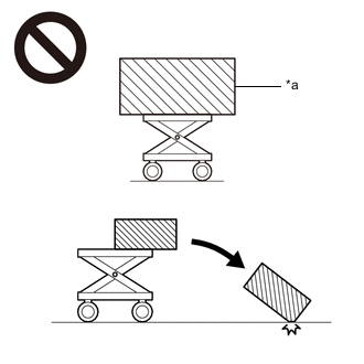
*a An Object Exceeding Weight Limit of Engine Lifter The engine assembly with hybrid vehicle transmission assembly is very heavy. Be sure to follow the procedure described in the repair manual, or the engine lifter may suddenly drop or the engine assembly with hybrid vehicle transmission assembly may fall off the engine lifter.
-
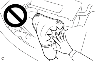
To prevent burns, do not touch the engine, exhaust manifold or other high temperature components while the engine is hot.
Note
After the power switch is turned off, the navigation system requires approximately a minute to record various types of memory and settings. As a result, after turning the power switch off, wait a minute or more before disconnecting the cable from the negative (-) auxiliary battery terminal.
| System Name | See Procedure |
|---|---|
| Vehicle enrolled in telematics system (w/ Telematics Transceiver for G-BOOK) | 6 minutes |
| Vehicle not enrolled in telematics system (w/ Telematics Transceiver for G-BOOK) | 1 minute |
PROCEDURE
-
PRECAUTION
-
PERFORM RESOLVER INITIALIZATION
-
ADJUST STANDARD VEHICLE HEIGHT (w/ Air Suspension)
-
REMOVE ENGINE ASSEMBLY WITH HYBRID VEHICLE TRANSMISSION
-
REMOVE MOTOR CABLE
CAUTION:
Wear insulated gloves.
Note
-
Cover the hole where the motor cable was connected with tape or equivalent (non-residue type) to prevent entry of foreign matter.
-
Insulate the removed terminals with insulating tape.
-
When removing the motor cable, make sure not to bend the motor cable base on the hybrid vehicle transmission assembly side.
-
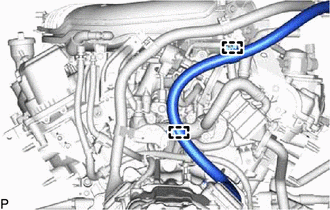
for LHD:
Disconnect the 2 clamps of the motor cable from the engine assembly.
-
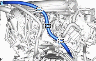
for RHD:
Disconnect the 3 clamps of the motor cable from the engine assembly.
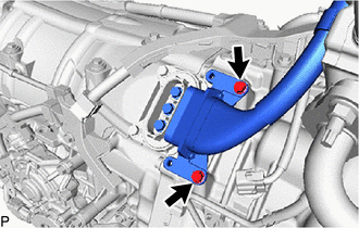
-
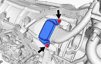
Using an insulated tool, remove the 2 bolts and connector cover from the hybrid vehicle transmission assembly.
-
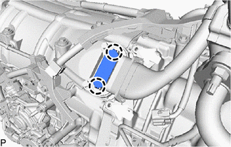
Using a screwdriver, detach the 2 claws to remove the terminal cap from the hybrid vehicle transmission assembly.
-
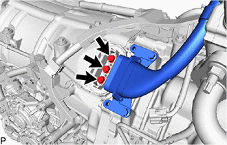
Using an insulated tool, remove the 3 bolts from the motor cable terminals.
-
Using an insulated tool, remove the 2 bolts and motor cable from the hybrid vehicle transmission assembly.
-