CAUTION / NOTICE / HINT
The necessary procedures (adjustment, calibration, initialization, or registration) that must be performed after parts are removed and installed, or replaced during the hybrid vehicle transmission assembly removal/installation are shown below.
After turning the power switch off, waiting time may be required before disconnecting the cable from the negative (-) auxiliary battery terminal. Therefore, make sure to read the disconnecting the cable from the negative (-) auxiliary battery terminal notices before proceeding with work.
| Replaced Part or Performed Procedure | Necessary Procedure | Effect/Inoperative Function when Necessary Procedure not Performed | Link |
|---|---|---|---|
| Auxiliary battery terminal is disconnected/reconnected | Memorize steering angle neutral point | LKA/LDA system (for Mono camera type) | for Stereo Camera type:Click here for Mono Camera type:Click here |
| Lane control system (for Stereo camera type) | |||
| Parking support brake system*1 | |||
| Pre-collision system (for Stereo camera type) | |||
| Pre-collision system (for Mono camera type) | |||
| Adaptive high beam system | |||
|
|||
| Variable gear ratio steering system | |||
| Parking assist monitor system | |||
| Panoramic view monitor system | |||
| Initialize rear door sunshade system | Rear door sunshade system | ||
| Initialize power trunk lid system | Power trunk lid system | ||
| ECM | Vehicle Identification Number (VIN) registration | DTC P063051 is output | w/ Canister Pump Module:Click here w/o Canister Pump Module:Click here |
|
Inspection after repair |
|
w/ Canister Pump Module:Click here w/o Canister Pump Module:Click here |
| Engine assembly | Inspection after repair | ||
| Drive learning*2 |
|
||
| Parts between the steering wheel and tires have been removed/installed, replaced or adjusted | Perform actuator angle neutral point calibration and initialization |
|
|
| Suspension, tires, etc |
|
Parking support brake system | |
|
Panoramic view monitor system | ||
| Rear television camera assembly optical axis (Back camera position setting) | Parking assist monitor system | ||
| Hybrid vehicle transmission assembly |
|
|
|
|
|
||
| Front bumper assembly (Including removal and installation) |
|
Parking support brake system | |
| Front television camera view adjustment | Panoramic view monitor system |
-
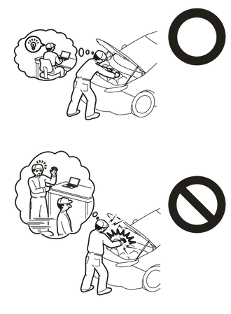
This vehicle has contains high voltage circuits standardized with orange colored wiring and connectors, so follow the instructions in this manual to perform the procedures correctly.
-
If the correct procedures are not followed according to the instructions in this manual, there is a danger of electric shock from the high voltage circuits.
-

Be sure to wear insulating gloves when working on high voltage wiring or components.
-
If work is performed without wearing insulating gloves, there is a danger of electric shock.
-
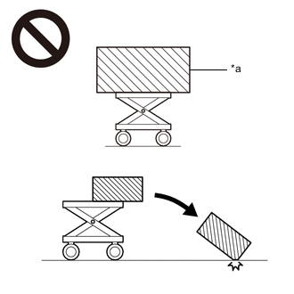
*a An Object Exceeding Weight Limit of Engine Lifter The engine assembly with hybrid vehicle transmission assembly is very heavy. Be sure to follow the procedure described in the repair manual, or the engine lifter may suddenly drop or the engine assembly with hybrid vehicle transmission assembly may fall off the engine lifter.
-
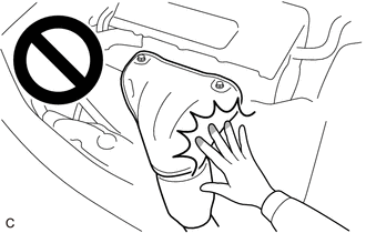
To prevent burns, do not touch the engine, exhaust manifold or other high temperature components while the engine is hot.
After the power switch is turned off, the navigation system requires approximately a minute to record various types of memory and settings. As a result, after turning the power switch off, wait a minute or more before disconnecting the cable from the negative (-) auxiliary battery terminal.
| System Name | See Procedure |
|---|---|
| Vehicle enrolled in telematics system (w/ Telematics Transceiver for G-BOOK) | 6 minutes |
| Vehicle not enrolled in telematics system (w/ Telematics Transceiver for G-BOOK) | 1 minute |
PROCEDURE
- Click here
PRECAUTION
- Click here
PERFORM RESOLVER INITIALIZATION
- Click here
ADJUST STANDARD VEHICLE HEIGHT (w/ Air Suspension)
- Click here
REMOVE ENGINE ASSEMBLY WITH HYBRID VEHICLE TRANSMISSION
- Click here
REMOVE NO. 1 EXHAUST PIPE SUPPORT BRACKET SUB-ASSEMBLY
-
Remove the 2 bolts and No. 1 exhaust pipe support bracket sub-assembly.
-
- Click here
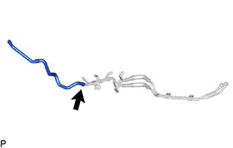
REMOVE NO. 1 EGR PIPE
- Click here
REMOVE EXHAUST MANIFOLD ASSEMBLY LH
- Click here
REMOVE EXHAUST MANIFOLD ASSEMBLY RH
- Click here
REMOVE GENERATOR CABLE
- Click here
REMOVE MOTOR CABLE
- Click here
DISCONNECT WIRE HARNESS
-
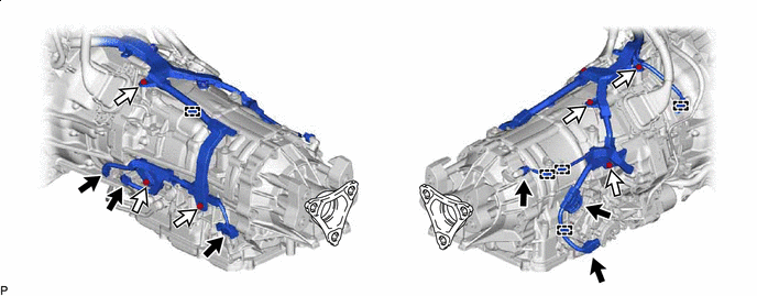

Wire Harness Connector 
Bolt Disconnect the 6 wire harness connectors.
-
Remove the 6 bolts and disconnect the 5 wire harness clamps from the hybrid vehicle transmission assembly.
-
- Click here
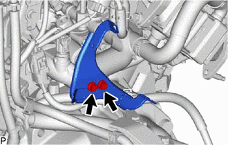
REMOVE TRANSMISSION OIL PUMP INSULATOR
-
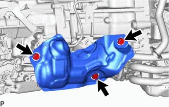
Remove the 3 bolts and transmission oil pump insulator.
-
- Click here
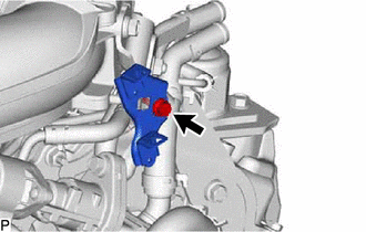
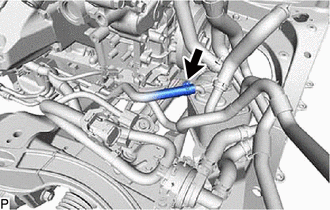
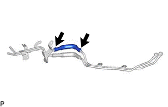
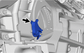
REMOVE NO. 2 TRANSMISSION BREATHER ASSEMBLY
-
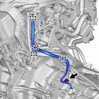
Disconnect the 4 clamps.
-
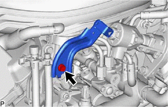
Remove the bolt and No. 2 transmission breather assembly.
-
Remove the O-ring from the No. 2 transmission breather assembly.
-
- Click here
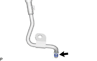
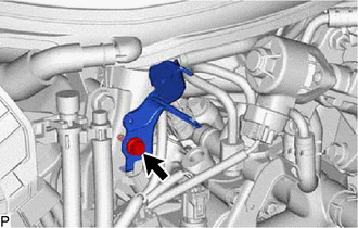
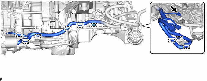
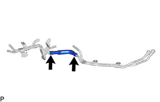
REMOVE NO. 1 TRANSMISSION BREATHER ASSEMBLY
-
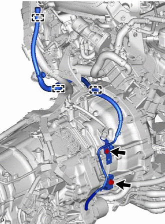
Disconnect the 3 clamps.
-
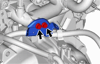
Remove the 2 bolts and No. 1 transmission breather assembly.
-
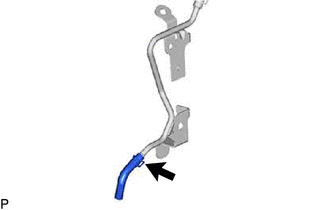
Slide the clip and remove the transmission breather hose from the No. 1 transmission breather assembly.
-
- Click here
REMOVE ENGINE MOTOR CABLE CLAMP BRACKET
-
for LHD:
-
Remove the bolt and engine motor cable clamp bracket.
-
Remove the 2 bolts and engine motor cable clamp bracket.
-
Remove the bolt and engine motor cable clamp bracket.
-
-
for RHD:
-
Remove the bolt and engine motor cable clamp bracket.
-
Remove the 2 bolts and engine motor cable clamp bracket.
-
-
- Click here
REMOVE WIRE HARNESS CLAMP BRACKET
-
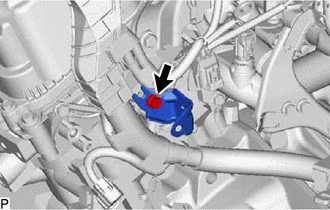
Remove the bolt and wire harness clamp bracket.
-
- Click here
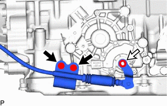
REMOVE OIL COOLER WITHOUT HOSE TUBE SUB-ASSEMBLY
-
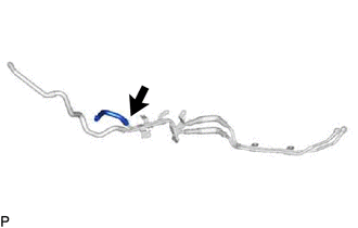
Slide the clip and disconnect the No. 2 oil cooler inlet hose from the motor cooling cooler.
-
Disconnect the oil pump thermistor connector.
-
Disconnect the 9 wire harness clamps.
-
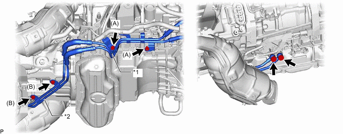
*1 Oil Cooler without Hose Tube Sub-assembly *2 Oil Cooler Union Sub-assembly Remove the 2 bolts (A), and disconnect the oil cooler without hose tube sub-assembly.
-
Remove the 2 union bolts, 4 gaskets, 2 bolts (B) and oil cooler union sub-assembly.
-
Slide the clip and remove the No. 2 oil cooler inlet hose from the oil cooler without hose tube sub-assembly.
-
Slide the clip and remove the No. 2 oil cooler outlet hose from the oil cooler without hose tube sub-assembly.
-
Slide the 2 clips and remove the No. 1 oil cooler inlet hose from the oil cooler without hose tube sub-assembly and oil cooler union sub-assembly.
-
Slide the 2 clips and remove the No. 1 oil cooler outlet hose from the oil cooler without hose tube sub-assembly and oil cooler union sub-assembly.
-
- Click here
REMOVE STARTER HOLE INSULATOR
-
Remove the 2 bolts and starter hole insulator.
-
- Click here
REMOVE FLYWHEEL HOUSING SIDE COVER
-
Remove the flywheel housing side cover from the engine assembly.
-
- Click here
REMOVE ENGINE REAR MOUNTING MEMBER
-
Bolt Nut and Spring Washer Remove the nut, spring washer and 2 bolts and disconnect the No. 2 parking lock release cable assembly from the shift control actuator assembly.
-
Remove the 3 nuts and engine rear mounting member.
-
- Click here
REMOVE REAR ENGINE MOUNTING INSULATOR
-
Remove the 4 bolts and rear engine mounting insulator.
-
- Click here
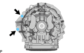
REMOVE HYBRID VEHICLE TRANSMISSION ASSEMBLY
-
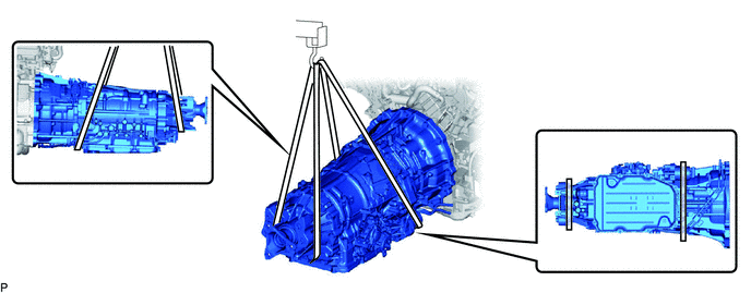
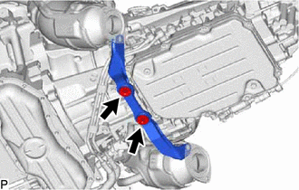
Using a rope or equivalent, support the hybrid vehicle transmission assembly at the positions shown in the illustration.
CAUTION:Secure the engine assembly to the engine lifter using a belt, etc. to prevent it from falling.
-
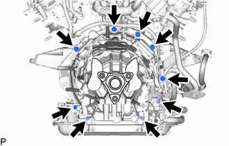
Remove the 9 bolts and hybrid vehicle transmission assembly from the engine assembly.
CAUTION:
-
Do not raise the hybrid vehicle transmission assembly more than necessary.
-
Make sure to confirm the center of the gravity of the hybrid vehicle transmission assembly when supporting it.
Note:Do not use excessive force to pry out the hybrid vehicle transmission assembly when separating it from the engine assembly to prevent the knock pins from being damaged.
-
-
- Click here
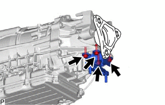
REMOVE BRACKET
-
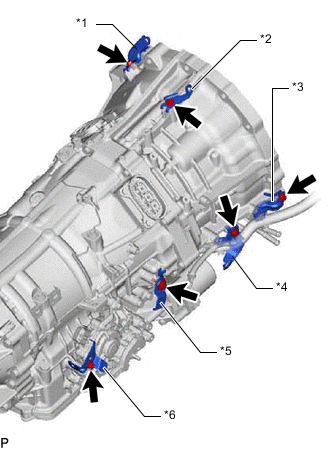
*1 No. 3 Wiring Harness Clamp Bracket *2 No. 2 Wiring Harness Clamp Bracket *3 Wiring Harness Clamp Bracket *4 No. 1 Wiring Harness Clamp Bracket *5 Transmission Oil Pump Insulator Bracket *6 No. 2 Heat Insulator Bracket Remove the 6 bolts and 6 brackets.
-
- Click here
REMOVE DYNAMIC DAMPER
-
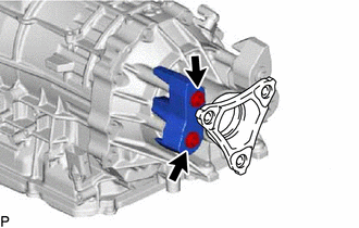
Using a T40 ''TORX'' socket wrench, remove the 2 bolts and dynamic damper.
-
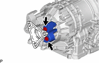
Using a T40 ''TORX'' socket wrench, remove the 2 bolts and dynamic damper.
-
- Click here
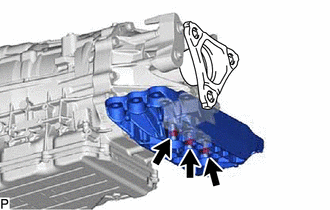
REMOVE AUTOMATIC TRANSMISSION CASE COVER
-
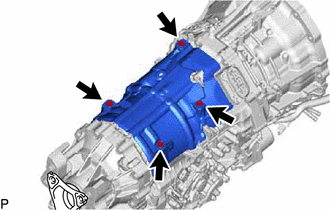
Remove the 4 bolts and automatic transmission case cover.
-