CAUTION / NOTICE / HINT
-
Be sure to read the "PRECAUTION" thoroughly before servicing.
-
In order to prevent the battery from becoming fully depleted, connect the battery charger to the auxiliary battery when turning the power switch on (IG) to charge the battery.
-
Keep the power supply connected to prevent the GTS battery from becoming fully depleted.
PROCEDURE
- Click here
AIR SUSPENSION CONTROL PROHIBITED
Tip:Check each part and system if an error is displayed for air movement pattern C.
-
Connect the GTS to the DLC3 with the power switch off.
-
Turn the power switch on (IG).
-
Turn the GTS on and enter the following menus: Chassis / Air suspension / Utility / Air Transfer Pattern C.
- Chassis > Air suspension > Utility
Tester Display Air Transfer Pattern C -
-
-
-
- Chassis > Air suspension > Utility
-
Perform vehicle height control prohibition and air movement according to the instructions on the GTS.
-
Discharge remaining pneumatic tank pressure:
-
Remove the luggage compartment floor mat.
-
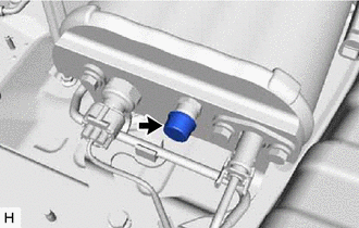
Remove the service valve cap.
-
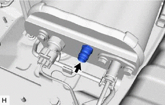
Discharge the remaining pressure by pushing the center of the service valve.
Tip:Do not release the remaining pressure at once. Release it over several steps.
-
Install the luggage compartment floor mat.
-
-
- Click here
REMOVE NO. 1 FLOOR UNDER COVER
- Click here
REMOVE W/O RELAY COMPRESSOR AND DRYER ASSEMBLY
Note:When discarding w/o relay compressor and dryer assembly, remove the No. 1 height control tube and No. 2 height control tube in order to release the pressure inside the compressor.
-

Disconnect the 2 connrctors.
-

Slide the clip and disconnect the height control hose from the height control wey.
-

*1 No. 5 height control tube *2 No. 9 height control tube Using SST, disconnect the No. 5 height control tube.
09730-00020 -
Using SST, disconnect the No. 9 height control tube.
09730-00020 -
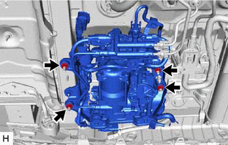
Remove the 4 bolts and w/o relay compressor and dryer assembly.
-

Detach the claw.
-
Rotate the clip and remove it from the stud bolt.
Tip:Leave the clip on the compressor.
-
- Click here
REMOVE HEIGHT CONTROL COMPRESSOR BRACKET
-

Remove the 2 nuts and height control compressor bracket.
-
- Click here
REMOVE NO. 2 HEIGHT CONTROL TUBE
-

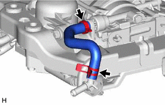
*a Natural *b Black Using SST, remove the No. 2 height control tube from the w/o relay compressor and dryer assembly and No. 3 height control valve assembly.
09730-00020 -
Detach the clamp from the No. 3 height control valve assembly
-
- Click here
REMOVE NO. 1 HEIGHT CONTROL TUBE
-

*a Natural *b Black Using SST, remove the No. 1 height control tube from the w/o relay compressor and dryer assembly and No. 3 height control valve assembly.
09730-00020
-
- Click here
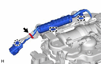
REMOVE HEIGHT CONTROL HOSE ASSEMBLY
-
Slide the clip and disconnect the height control hose from the height control wey.
-
Cut the cable tie.
-
Remove the height control hose from the w/o relay compressor and dryer assembly.
-
- Click here
REMOVE HEIGHT CONTROL WAY
-

Detach the claw and remove the height control way from the compressor bracket.
-
- Click here
REMOVE HEIGHT CONTROL VALVE HARNESS ASSEMBLY
-

Disconnect the 3 connectors.
-
Detach the 2 clamps.
-
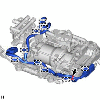
Disconnect the 9 clamps and remove the height control valve harness assembly.
-
Cut the cable tie.
-
- Click here
REMOVE NO. 1 HEIGHT CONTROL COMPRESSOR
-
Disconnect the 2 clamps.
-
Detach the claw and disconnect the connector.
-
Cut the cable tie.
-

*1 Plate Washer *2 Height Control Compressor Bush *3 Collar *4 Height Control Compressor Compression Spring Remove the 3 nuts, No. 3 height control compressor bracket and No. 1 height control compressor.
-
Remove the plate washer, collar, 5 height control compressor bushes and 5 height control compressor compression spring.
-
- Click here
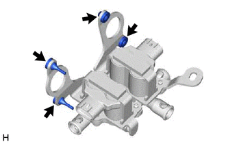
REMOVE NO. 3 HEIGHT CONTROL VALVE
-

Remove the 2 nuts, height control valve bracket and No. 3 height control valve assembly.
-

*1 Height Control Valve Bush 
No. 1 Height Control Compressor Side Remove the 2 height control valve bushes.
-
Remove the 4 height control valve cushions.
-