DYNAMIC RADAR CRUISE CONTROL SYSTEM, Diagnostic DTC:P0571
| DTC Code | DTC Name |
|---|---|
| P0571 | Brake Switch "A" Circuit |
DESCRIPTION
Condition 1:
-
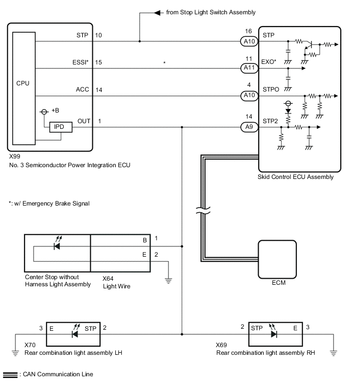
The ECM receives the brake demand signal from the driving support ECU assembly and sends it to the skid control ECU assembly. The skid control ECU assembly receives the signal from the ECM and operates the skid control ECU assembly. The skid control ECU assembly operates the brake actuator and at the same time illuminates the stop lights by operating the No. 3 semiconductor power integration ECU.
Condition 2:
-
When the brake pedal is depressed, the stop light switch assembly sends a signal to the ECM. When the ECM receives this signal, it cancels the dynamic radar cruise control. The fail-safe function operates to enable normal driving even if there is a malfunction in the stop light signal circuit. The cancellation condition occurs when voltage is applied to terminal STP. When the brake is applied, voltage is applied to terminal STP of the ECM through the STOP fuse and the stop light switch assembly, and the ECM turns the dynamic radar cruise control system off.
| DTC No. | Detection Item | DTC Detection Condition | Trouble Area |
|---|---|---|---|
| P0571 | Brake Switch "A" Circuit | Condition 1:
Condition 2:
|
Condition 1:
Condition 2:
|
WIRING DIAGRAM
CAUTION / NOTICE / HINT
Note
First check the CAN communication system by following How to Proceed with Troubleshooting. After checking that there are no malfunctions in the CAN communication system, proceed with troubleshooting.
PROCEDURE
-
CHECK FOR DTCs (SFI SYSTEM)
-
Check for DTCs.
w/ Canister Pump Module: Click here
w/o Canister Pump Module: Click here
Powertrain > Engine > Trouble CodesTech Tips
Dynamic radar cruise control system DTC P0571 may be stored due to a malfunction in the SFI system. Therefore it is necessary to check for and troubleshoot SFI system DTCs first.
Result Result Proceed to SFI system DTCs are not output A SFI system DTCs are output B
B 
GO TO SFI SYSTEM w/ Canister Pump Module: Click here
GO TO SFI SYSTEM w/o Canister Pump Module: Click hereA 
-
-
CHECK FOR DTCs (POWER INTEGRATION SYSTEM)
-
Check for DTCs.
Body Electrical > Power Integration No.3 > Trouble CodesTech Tips
If there is a malfunction in the No. 3 semiconductor integration ECU, integration relay system DTCs may also have been detected. Check the integration relay system first.
Result Result Proceed to Power integration system DTCs are not output A Power integration system DTCs are output B
B
GO TO POWER INTEGRATION SYSTEM Click here
A
-
-
READ VALUE USING GTS (STOP LIGHT INPUT SIGNAL, STOP LIGHT OUTPUT SIGNAL AND STATUS OF STOP LIGHT FUSE)
-
Using the GTS, check the Data List "Stop Light Input Signal", "Stop Light Output Signal" and "Status of Stop Light Fuse" with the brake pedal operated.
Body Electrical > Power Integration No.3 > Data ListTester Display Measurement Item Range Normal Condition Diagnostic Note Stop Light Input Signal Stop light switch assembly input condition ON or OFF ON: Brake pedal depressed
OFF: Brake pedal released
- Stop Light Output Signal Stop light output condition ON or OFF ON: Stop light is on
OFF: Stop light is off
Stop lights blink during emergency brake signal control Status of Stop Light Fuse Stop light fuse condition Disconnect or Connect Disconnect: Fuse shut off
Connect: Fuse not shut off
-
Body Electrical > Power Integration No.3 > Data ListTester Display Stop Light Input Signal Stop Light Output Signal Status of Stop Light Fuse Standard Brake pedal operation Data List Display Condition Stop Light Input Signal Stop Light Output Signal Status of Stop Light Fuse Brake pedal depressed ON ON Connect Result Brake pedal operation Data List Display Condition Result Stop Light Input Signal Stop Light Output Signal Status of Stop Light Fuse Brake pedal depressed ON ON Connect A ON OFF Connect B ON OFF Disconnect C OFF OFF Connect D
B
GO TO POWER INTEGRATION SYSTEM Click here
C 
READ VALUE USING GTS (STOP LIGHT OUTPUT SIGNAL AND STATUS OF STOP LIGHT FUSE) Click here
D
CHECK TERMINAL VOLTAGE (STP TERMINAL) Click here
A
-
-
CHECK TERMINAL VOLTAGE (STP, STPO AND STP2 TERMINAL)
-
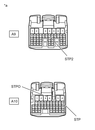
*a Front view of wire harness connector
(to Skid Control ECU Assembly)
Disconnect the A9 and A10 skid control ECU assembly connectors.
-
Measure the voltage according to the value(s) in the table below.
Standard Voltage Tester Connection Condition Specified Condition A10-16(STP) - Body ground Brake pedal depressed 8 to 14 V Brake pedal released Below 1.5 V A10-4(STPO) - Body ground Engine switch off 8 to 14 V A9-14(STP2) - Body ground Brake pedal depressed 8 to 14 V Brake pedal released Below 1.5 V -
Connect the A9 and A10 skid control ECU assembly connectors.
Result Result Proceed to All terminal voltage is normal A Only STP terminal voltage abnormal B Only STPO terminal voltage abnormal C Only STP2 terminal voltage abnormal D STPO terminal and STP2 terminal voltage abnormal E
B
REPAIR OR REPLACE HARNESS OR CONNECTOR
C
CHECK HARNESS AND CONNECTOR (SKID CONTROL ECU ASSEMBLY - NO. 3 SEMICONDUCTOR POWER INTEGRATION ECU) Click here
D
CHECK TERMINAL VOLTAGE (STP2 TERMINAL) Click here
E
CHECK HARNESS AND CONNECTOR (SKID CONTROL ECU ASSEMBLY - NO. 3 SEMICONDUCTOR POWER INTEGRATION ECU) Click here
A
-
-
PERFORM ACTIVE TEST USING GTS (STOP LIGHT RELAY)
-
Enter the following menus: Chassis / ABS/VSC/TRC / Active Test.
-
Perform "Active Test" according to the display on the GTS.
Chassis > ABS/VSC/TRC > Active TestTester Display Measurement Item Control Range Diagnostic Note Stop Light Relay No. 3 semiconductor power integration ECU ECU (Stop light output) ON/OFF Stop lights come on
Chassis > ABS/VSC/TRC > Active TestTester Display Stop Light Relay OK Stop light turns ON/OFF in response to the GTS operation Result Proceed to OK NG
NG
INSPECT SKID CONTROL ECU ASSEMBLY Click here
OK
-
-
CHECK FOR DTCs (RADAR CRUISE 1)
-
Clear the DTCs.
Powertrain > Radar Cruise1 > Clear DTCs -
Enter the following menus: Chassis / ABS/VSC/TRC / Active Test.
-
Perform "Active Test" according to the display on the GTS.
Chassis > ABS/VSC/TRC > Active TestTester Display Measurement Item Control Range Diagnostic Note Stop Light Relay No. 3 semiconductor power integration ECU ECU (Stop light output) ON/OFF Stop lights come on
Chassis > ABS/VSC/TRC > Active TestTester Display Stop Light Relay -
Check for DTCs.
Powertrain > Radar Cruise1 > Trouble CodesResult Result Proceed to DTC P0571 is not output A DTC P0571 is output B
A
USE SIMULATION METHOD TO CHECK Click here
B
REPLACE SKID CONTROL ECU ASSEMBLY for LHD: Click here
REPLACE SKID CONTROL ECU ASSEMBLY for RHD: Click here -
-
INSPECT SKID CONTROL ECU ASSEMBLY
-
Enter the following menus: Chassis / ABS/VSC/TRC / Active Test.
-
Perform "Active Test" according to the display on the GTS.
Chassis > ABS/VSC/TRC > Active TestTester Display Measurement Item Control Range Diagnostic Note Stop Light Relay No. 3 semiconductor power integration ECU ECU (Stop light output) ON/OFF Stop lights come on
Chassis > ABS/VSC/TRC > Active TestTester Display Stop Light Relay -
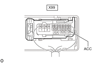
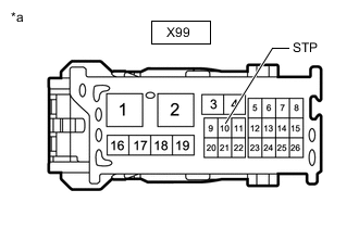
*a Component with harness connected
(No. 3 Semiconductor Power Integration ECU)
Measure the voltage according to the value(s) in the table below.
Standard Voltage Tester Connection Condition Specified Condition X99-14(ACC) - Body ground Active test is ON Below 1.5 V Result Proceed to OK NG
OK
GO TO POWER INTEGRATION SYSTEM Click here
NG
REPLACE SKID CONTROL ECU ASSEMBLY for LHD: Click here
REPLACE SKID CONTROL ECU ASSEMBLY for RHD: Click here -
-
CHECK HARNESS AND CONNECTOR (SKID CONTROL ECU ASSEMBLY - NO. 3 SEMICONDUCTOR POWER INTEGRATION ECU)
-
Disconnect the A10 skid control ECU assembly connector.
-
Disconnect the X99 No. 3 semiconductor power integration ECU connector.
-
Measure the resistance according to the value(s) in the table below.
Standard Resistance Tester Connection Condition Specified Condition A10-4(STPO) - X99-14(ACC) Always Below 1 Ω -
Connect the X99 No. 3 semiconductor power integration ECU connector.
-
Connect the A10 skid control ECU assembly connector.
Result Proceed to OK NG
OK
GO TO POWER INTEGRATION SYSTEM Click here
NG
REPAIR OR REPLACE HARNESS OR CONNECTOR (SKID CONTROL ECU ASSEMBLY - NO. 3 SEMICONDUCTOR POWER INTEGRATION ECU)
-
-
CHECK TERMINAL VOLTAGE (STP2 TERMINAL)
-
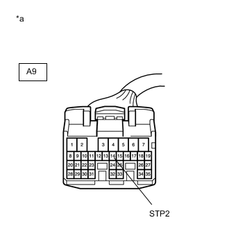
*a Front view of wire harness connector
(to Skid Control ECU Assembly)
Disconnect the A9 skid control ECU assembly connector.
-
Measure the voltage according to the value(s) in the table below.
Standard Voltage Tester Connection Condition Specified Condition A9-14(STP2) - Body ground Brake pedal released Below 1.5 V -
Connect the A9 skid control ECU assembly connector.
Result Proceed to OK NG
NG
CHECK HARNESS AND CONNECTOR (SKID CONTROL ECU ASSEMBLY - NO. 3 SEMICONDUCTOR POWER INTEGRATION ECU) Click here
OK
-
-
CHECK HARNESS AND CONNECTOR (SKID CONTROL ECU ASSEMBLY - NO. 3 SEMICONDUCTOR POWER INTEGRATION ECU)
-
Disconnect the X70 rear combination light assembly LH connector.
-
Disconnect the X69 rear combination light assembly RH connector.
-
Disconnect the X64 light wire econnector.
-
Disconnect the X99 No. 3 semiconductor power integration ECU connector.
-
Disconnect the A9 skid control ECU assembly connector.
-
Measure the resistance according to the value(s) in the table below.
Standard Resistance Tester Connection Condition Specified Condition X99-1(OUT) - A9-14(STP2) Always Below 1 Ω -
Connect the A9 skid control ECU assembly connector.
-
Connect the X99 No. 3 semiconductor power integration ECU connector.
-
Connect the X64 light wire econnector.
-
Connect the X69 rear combination light assembly RH connector.
-
Connect the X70 rear combination light assembly LH connector.
Result Proceed to OK NG
OK
GO TO POWER INTEGRATION SYSTEM Click here
NG
REPAIR OR REPLACE HARNESS OR CONNECTOR (SKID CONTROL ECU ASSEMBLY - NO. 3 SEMICONDUCTOR POWER INTEGRATION ECU)
-
-
CHECK HARNESS AND CONNECTOR (SKID CONTROL ECU ASSEMBLY - NO. 3 SEMICONDUCTOR POWER INTEGRATION ECU)
-
Disconnect the A9 skid control ECU assembly connector.
-
Disconnect the X99 No. 3 semiconductor power integration ECU connector.
-
Measure the voltage according to the value(s) in the table below.
Standard Voltage Tester Connection Condition Specified Condition A9-14(STP2) - Body ground Brake pedal released Below 1.5 V -
Connect the X99 No. 3 semiconductor power integration ECU connector.
-
Connect the A9 skid control ECU assembly connector.
Result Proceed to OK NG
OK
GO TO POWER INTEGRATION SYSTEM Click here
NG
-
-
CHECK HARNESS AND CONNECTOR (SKID CONTROL ECU ASSEMBLY - REAR COMBINATION LIGHT ASSEMBLY LH)
-
Disconnect the A9 skid control ECU assembly connector.
-
Disconnect the X99 No. 3 semiconductor power integration ECU connector.
-
Disconnect the X70 rear combination light assembly LH connector.
-
Measure the voltage according to the value(s) in the table below.
Standard Voltage Tester Connection Condition Specified Condition A9-14(STP2) - Body ground Brake pedal released Below 1.5 V -
Connect the X70 rear combination light assembly LH connector.
-
Connect the X99 No. 3 semiconductor power integration ECU connector.
-
Connect the A9 skid control ECU assembly connector.
Result Proceed to OK NG
OK
REPLACE REAR COMBINATION LIGHT ASSEMBLY LH Click here
NG
-
-
CHECK HARNESS AND CONNECTOR (SKID CONTROL ECU ASSEMBLY - REAR COMBINATION LIGHT ASSEMBLY RH)
-
Disconnect the A9 skid control ECU assembly connector.
-
Disconnect the X99 No. 3 semiconductor power integration ECU connector.
-
Disconnect the X70 rear combination light assembly LH connector.
-
Disconnect the X69 rear combination light assembly RH connector.
-
Measure the voltage according to the value(s) in the table below.
Standard Voltage Tester Connection Condition Specified Condition A9-14(STP2) - Body ground Brake pedal released Below 1.5 V -
Connect the X69 rear combination light assembly RH connector.
-
Connect the X70 rear combination light assembly LH connector.
-
Connect the X99 No. 3 semiconductor power integration ECU connector.
-
Connect the A9 skid control ECU assembly connector.
Result Proceed to OK NG
OK
REPLACE REAR COMBINATION LIGHT ASSEMBLY RH Click here
NG
CHECK HARNESS AND CONNECTOR (SKID CONTROL ECU ASSEMBLY - CENTER STOP WITHOUT HARNESS LIGHT ASSEMBLY) Click here
-
-
CHECK HARNESS AND CONNECTOR (SKID CONTROL ECU ASSEMBLY - NO. 3 SEMICONDUCTOR POWER INTEGRATION ECU)
-
Disconnect the A10 skid control ECU assembly connector.
-
Disconnect the X99 No. 3 semiconductor power integration ECU connector.
-
Measure the resistance according to the value(s) in the table below.
Standard Resistance Tester Connection Condition Specified Condition A10-4(STPO) or X99-14(ACC) - Body ground Always 10 kΩ or higher -
Connect the X99 No. 3 semiconductor power integration ECU connector.
-
Connect the A10 skid control ECU assembly connector.
Result Proceed to OK NG
OK
GO TO POWER INTEGRATION SYSTEM Click here
NG
REPAIR OR REPLACE HARNESS OR CONNECTOR (SKID CONTROL ECU ASSEMBLY - NO. 3 SEMICONDUCTOR POWER INTEGRATION ECU)
-
-
CHECK HARNESS AND CONNECTOR (SKID CONTROL ECU ASSEMBLY - CENTER STOP WITHOUT HARNESS LIGHT ASSEMBLY)
-
Disconnect the A9 skid control ECU assembly connector.
-
Disconnect the X99 No. 3 semiconductor power integration ECU connector.
-
Disconnect the X70 rear combination light assembly LH connector.
-
Disconnect the X69 rear combination light assembly RH connector.
-
Disconnect the center stop without harness light assembly connector.
-
Measure the voltage according to the value(s) in the table below.
Standard Voltage Tester Connection Condition Specified Condition A9-14(STP2) - Body ground Brake pedal released Below 1.5 V -
Connect the center stop without harness light assembly connector.
-
Connect the X69 rear combination light assembly RH connector.
-
Connect the X70 rear combination light assembly LH connector.
-
Connect the X99 No. 3 semiconductor power integration ECU connector.
-
Connect the A9 skid control ECU assembly connector.
Result Proceed to OK NG
OK
REPLACE CENTER STOP WITHOUT HARNESS LIGHT ASSEMBLY Click here
NG
CHECK HARNESS AND CONNECTOR (SKID CONTROL ECU ASSEMBLY - LIGHT WIRE) Click here
-
-
READ VALUE USING GTS (STOP LIGHT OUTPUT SIGNAL AND STATUS OF STOP LIGHT FUSE)
-
Disconnect the X70 rear combination light assembly LH connector.
-
Using the GTS, check the Data List "Stop Light Output Signal" and "Status of Stop Light Fuse" with the brake pedal operated.
Body Electrical > Power Integration No.3 > Data ListTester Display Measurement Item Range Normal Condition Diagnostic Note Stop Light Output Signal Stop light output condition ON or OFF ON: Stop light is on
OFF: Stop light is off
Stop lights blink during emergency brake signal control Status of Stop Light Fuse Stop light fuse condition Disconnect or Connect Disconnect: Fuse shut off
Connect: Fuse not shut off
-
Body Electrical > Power Integration No.3 > Data ListTester Display Stop Light Output Signal Status of Stop Light Fuse Standard Brake pedal operation Data List Display Condition Stop Light Output Signal Status of Stop Light Fuse Brake pedal depressed ON Connect -
Connect the X70 rear combination light assembly LH connector.
Result Brake pedal operation Data List Display Condition Result Stop Light Output Signal Status of Stop Light Fuse Brake pedal depressed ON Connect A OFF Disconnect B
A
REPLACE REAR COMBINATION LIGHT ASSEMBLY LH Click here
B
READ VALUE USING GTS (STOP LIGHT OUTPUT SIGNAL AND STATUS OF STOP LIGHT FUSE) Click here
-
-
CHECK HARNESS AND CONNECTOR (SKID CONTROL ECU ASSEMBLY - LIGHT WIRE)
-
Disconnect the A9 skid control ECU assembly connector.
-
Disconnect the X99 No. 3 semiconductor power integration ECU connector.
-
Disconnect the X70 rear combination light assembly LH connector.
-
Disconnect the X69 rear combination light assembly RH connector.
-
Disconnect the X64 light wire connector.
-
Measure the voltage according to the value(s) in the table below.
Standard Voltage Tester Connection Condition Specified Condition A9-14(STP2) - Body ground Brake pedal released Below 1.5 V -
Connect the X64 light wire connector.
-
Connect the X69 rear combination light assembly RH connector.
-
Connect the X70 rear combination light assembly LH connector.
-
Connect the X99 No. 3 semiconductor power integration ECU connector.
-
Connect the A9 skid control ECU assembly connector.
Result Proceed to OK NG
OK
REPLACE LIGHT WIRE Click here
NG
REPAIR OR REPLACE HARNESS OR CONNECTOR (SKID CONTROL ECU ASSEMBLY - LIGHT WIRE)
-
-
READ VALUE USING GTS (STOP LIGHT OUTPUT SIGNAL AND STATUS OF STOP LIGHT FUSE)
-
Disconnect the X70 rear combination light assembly LH connector.
-
Disconnect the X69 rear combination light assembly RH connector.
-
Using the GTS, check the Data List "Stop Light Output Signal" and "Status of Stop Light Fuse" with the brake pedal operated.
Body Electrical > Power Integration No.3 > Data ListTester Display Measurement Item Range Normal Condition Diagnostic Note Stop Light Output Signal Stop light output condition ON or OFF ON: Stop light is on
OFF: Stop light is off
Stop lights blink during emergency brake signal control Status of Stop Light Fuse Stop light fuse condition Disconnect or Connect Disconnect: Fuse shut off
Connect: Fuse not shut off
-
Body Electrical > Power Integration No.3 > Data ListTester Display Stop Light Output Signal Status of Stop Light Fuse Standard Brake pedal operation Data List Display Condition Stop Light Output Signal Status of Stop Light Fuse Brake pedal depressed ON Connect -
Connect the X69 rear combination light assembly RH connector.
-
Connect the X70 rear combination light assembly LH connector.
Result Brake pedal operation Data List Display Condition Result Stop Light Output Signal Status of Stop Light Fuse Brake pedal depressed ON Connect A OFF Disconnect B
A
REPLACE REAR COMBINATION LIGHT ASSEMBLY RH Click here
B
-
-
READ VALUE USING GTS (STOP LIGHT OUTPUT SIGNAL AND STATUS OF STOP LIGHT FUSE)
-
Disconnect the X70 rear combination light assembly LH connector.
-
Disconnect the X69 rear combination light assembly RH connector.
-
Disconnect the center stop without harness light assembly connector.
-
Using the GTS, check the Data List "Stop Light Output Signal" and "Status of Stop Light Fuse" with the brake pedal operated.
Body Electrical > Power Integration No.3 > Data ListTester Display Measurement Item Range Normal Condition Diagnostic Note Stop Light Output Signal Stop light output condition ON or OFF ON: Stop light is on
OFF: Stop light is off
Stop lights blink during emergency brake signal control Status of Stop Light Fuse Stop light fuse condition Disconnect or Connect Disconnect: Fuse shut off
Connect: Fuse not shut off
-
Body Electrical > Power Integration No.3 > Data ListTester Display Stop Light Output Signal Status of Stop Light Fuse Standard Brake pedal operation Data List Display Condition Stop Light Output Signal Status of Stop Light Fuse Brake pedal depressed ON Connect -
Connect the center stop without harness light assembly connector.
-
Connect the X69 rear combination light assembly RH connector.
-
Connect the X70 rear combination light assembly LH connector.
Result Brake pedal operation Data List Display Condition Result Stop Light Output Signal Status of Stop Light Fuse Brake pedal depressed ON Connect A OFF Disconnect B
A
REPLACE CENTER STOP WITHOUT HARNESS LIGHT ASSEMBLY Click here
B
READ VALUE USING GTS (STOP LIGHT OUTPUT SIGNAL AND STATUS OF STOP LIGHT FUSE) Click here
-
-
CHECK TERMINAL VOLTAGE (STP TERMINAL)
-
*a Front view of wire harness connector
(to No. 3 Semiconductor Power Integration ECU)
Disconnect the X99 No. 3 semiconductor power integration ECU connector.
-
Measure the voltage according to the value(s) in the table below.
Standard Voltage Tester Connection Condition Specified Condition X99-10 (STP) - Body ground Brake pedal depressed Below 1.5 V -
Connect the X99 No. 3 semiconductor power integration ECU connector.
Result Proceed to OK NG
OK
GO TO POWER INTEGRATION SYSTEM Click here
NG
REPAIR OR REPLACE HARNESS OR CONNECTOR (STOP LIGHT SWITCH ASSEMBLY - NO. 3 SEMICONDUCTOR POWER INTEGRATION ECU)
-
-
READ VALUE USING GTS (STOP LIGHT OUTPUT SIGNAL AND STATUS OF STOP LIGHT FUSE)
-
Disconnect the X70 rear combination light assembly LH connector.
-
Disconnect the X69 rear combination light assembly RH connector.
-
Disconnect the X64 light wire connector.
-
Using the GTS, check the Data List "Stop Light Output Signal" and "Status of Stop Light Fuse" with the brake pedal operated.
Body Electrical > Power Integration No.3 > Data ListTester Display Measurement Item Range Normal Condition Diagnostic Note Stop Light Output Signal Stop light output condition ON or OFF ON: Stop light is on
OFF: Stop light is off
Stop lights blink during emergency brake signal control Status of Stop Light Fuse Stop light fuse condition Disconnect or Connect Disconnect: Fuse shut off
Connect: Fuse not shut off
-
Body Electrical > Power Integration No.3 > Data ListTester Display Stop Light Output Signal Status of Stop Light Fuse Standard Brake pedal operation Data List Display Condition Stop Light Output Signal Status of Stop Light Fuse Brake pedal depressed ON Connect -
Connect the X64 light wire connector.
-
Connect the X69 rear combination light assembly RH connector.
-
Connect the X70 rear combination light assembly LH connector.
Result Brake pedal operation Data List Display Condition Result Stop Light Output Signal Status of Stop Light Fuse Brake pedal depressed ON Connect A OFF Disconnect B
A
REPLACE LIGHT WIRE Click here
B
-
-
READ VALUE USING GTS (STOP LIGHT OUTPUT SIGNAL AND STATUS OF STOP LIGHT FUSE)
-
Disconnect the X70 rear combination light assembly LH connector.
-
Disconnect the X69 rear combination light assembly RH connector.
-
Disconnect the X64 light wire connector.
-
Disconnect the A9 skid control ECU assembly connector.
-
Using the GTS, check the Data List "Stop Light Output Signal" and "Status of Stop Light Fuse" with the brake pedal operated.
Body Electrical > Power Integration No.3 > Data ListTester Display Measurement Item Range Normal Condition Diagnostic Note Stop Light Output Signal Stop light output condition ON or OFF ON: Stop light is on
OFF: Stop light is off
Stop lights blink during emergency brake signal control Status of Stop Light Fuse Stop light fuse condition Disconnect or Connect Disconnect: Fuse shut off
Connect: Fuse not shut off
-
Body Electrical > Power Integration No.3 > Data ListTester Display Stop Light Output Signal Status of Stop Light Fuse Standard Brake pedal operation Data List Display Condition Stop Light Output Signal Status of Stop Light Fuse Brake pedal depressed ON Connect -
Connect the A9 skid control ECU assembly connector.
-
Connect the X64 light wire connector.
-
Connect the X69 rear combination light assembly RH connector.
-
Connect the X70 rear combination light assembly LH connector.
Result Brake pedal operation Data List Display Condition Result Stop Light Output Signal Status of Stop Light Fuse Brake pedal depressed ON Connect A OFF Disconnect B
A
REPLACE SKID CONTROL ECU ASSEMBLY for LHD: Click here
REPLACE SKID CONTROL ECU ASSEMBLY for RHD: Click hereB
-
-
CHECK HARNESS AND CONNECTOR (SKID CONTROL ECU ASSEMBLY - NO. 3 SEMICONDUCTOR POWER INTEGRATION ECU)
-
Disconnect the X70 rear combination light assembly LH connector.
-
Disconnect the X69 rear combination light assembly RH connector.
-
Disconnect the X64 light wire connector.
-
Disconnect the A9 skid control ECU assembly connector.
-
Disconnect the X99 No. 3 semiconductor power integration ECU connector.
-
Measure the resistance according to the value(s) in the table below.
Standard Resistance Tester Connection Condition Specified Condition X99-1 (OUT) or A9-14 (STP2) - Body ground Always 10 kΩ or higher -
Connect the X99 No. 3 semiconductor power integration ECU connector.
-
Connect the A9 skid control ECU assembly connector.
-
Connect the X64 light wire connector.
-
Connect the X69 rear combination light assembly RH connector.
-
Connect the X70 rear combination light assembly LH connector.
Result Proceed to OK NG
OK
GO TO POWER INTEGRATION SYSTEM Click here
NG
REPAIR OR REPLACE HARNESS OR CONNECTOR (SKID CONTROL ECU ASSEMBLY - NO. 3 SEMICONDUCTOR POWER INTEGRATION ECU)
-