CAN COMMUNICATION SYSTEM Check Bus 5 Lines for Short Circuit
DESCRIPTION
There may be a short circuit between the CAN main bus lines and/or CAN branch lines when the resistance between terminals 15 (CA5H) and 16 (CA5L) of the central gateway ECU (network gateway ECU) is below 54 Ω.
| Symptom | Trouble Area |
|---|---|
| Resistance between terminals 15 (CA5H) and 16 (CA5L) of the central gateway ECU (network gateway ECU) is below 54 Ω. |
|
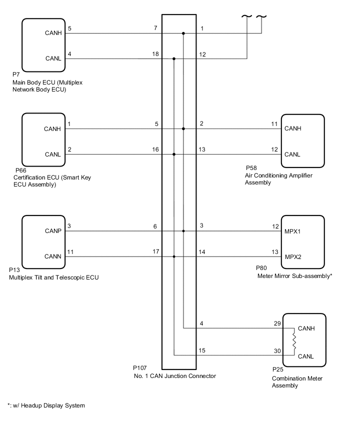
*2: w/ Headup Display System
WIRING DIAGRAM
-
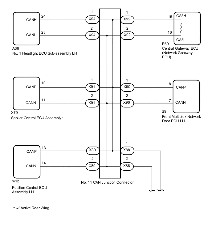
for LHD
-
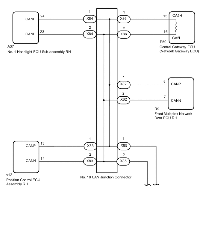
for RHD
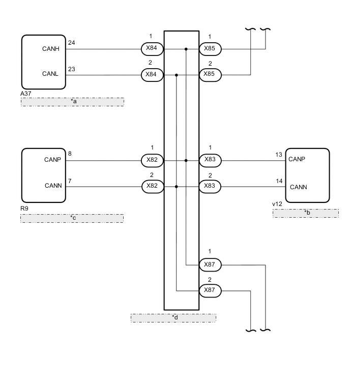
*a No. 1 Headlight ECU Sub-assembly RH *b Position Control ECU Assembly RH *c Front Multiplex Network Door ECU RH *d No. 10 CAN Junction Connector
CAUTION / NOTICE / HINT
CAUTION:
When performing the confirmation driving pattern, obey all speed limits and traffic laws.
Note
-
Because the order of diagnosis is important to allow correct diagnosis, make sure to begin troubleshooting using How to Proceed with Troubleshooting when CAN communication system related DTCs are output.
-
Before measuring the resistance of the CAN bus, turn the engine switch off and leave the vehicle for 1 minute or more without operating the key or any switches, or opening or closing the doors. After that, disconnect the cable from the negative (-) battery terminal and leave the vehicle for 1 minute or more before measuring the resistance.
-
After turning the engine switch off, waiting time may be required before disconnecting the cable from the negative (-) battery terminal. Therefore, make sure to read the disconnecting the cable from the negative (-) battery terminal notices before proceeding with work.
-
Some parts must be initialized and set when replacing or removing and installing parts.
-
After performing repairs, perform the DTC check procedure and confirm that the DTCs are not output again.
DTC check procedure: Turn the engine switch on (IG) and wait for 1 minute or more. Then operate the suspected malfunctioning system and drive the vehicle at 60 km/h (37 mph) or more for 5 minutes or more.
-
After the repair, perform the CAN bus check and check that all the ECUs and sensors connected to the CAN communication system are displayed as normal.
-
When replacing the combination meter assembly, always replace it with a new one. If a combination meter assembly which was installed to another vehicle is used, the information stored in it will not match the information from the vehicle and a DTC may be stored.
-
Before replacing the certification ECU (smart key ECU assembly), refer to the entry and start system.
Tech Tips
-
Before disconnecting related connectors for inspection, push in on each connector body to check that the connector is not loose or disconnected.
-
When a connector is disconnected, check that the terminals and connector body are not cracked, deformed or corroded.
PROCEDURE
-
CHECK FOR SHORT IN CAN BUS WIRES (COMBINATION METER ASSEMBLY - NO. 1 CAN JUNCTION CONNECTOR)
-
Disconnect the cable from the negative (-) battery terminal.
-
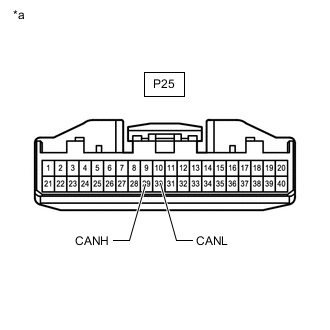
*a Front view of wire harness connector
(to Combination Meter Assembly)
Disconnect the combination meter assembly connector.
-
Measure the resistance according to the value(s) in the table below.
Standard Resistance Tester Connection Condition Specified Condition P25-29 (CANH) - P25-30 (CANL) Cable disconnected from negative (-) battery terminal 108 to 132 Ω Result Result Proceed to OK A NG (for LHD) B NG (for RHD) C
A 
REPLACE COMBINATION METER ASSEMBLY Click here
C 
CONNECT CONNECTOR Click here
B 
-
-
CONNECT CONNECTOR
-
Reconnect the P25 combination meter assembly connector.
Result Proceed to NEXT
NEXT
-
-
CHECK FOR SHORT IN CAN BUS WIRES (CENTRAL GATEWAY ECU [NETWORK GATEWAY ECU] - NO. 10 CAN JUNCTION CONNECTOR)
-
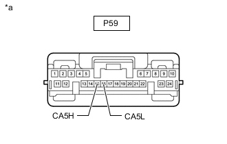
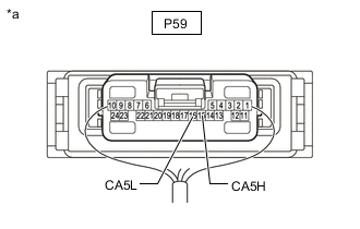
*a Front view of wire harness connector
(to Central Gateway ECU [Network Gateway ECU])
Disconnect the central gateway ECU (network gateway ECU) connector.
-
Measure the resistance according to the value(s) in the table below.
Standard Resistance Tester Connection Condition Specified Condition P59-15 (CA5H) - P59-16 (CA5L) Cable disconnected from negative (-) battery terminal 108 to 132 Ω Result Result OK NG
OK
REPLACE CENTRAL GATEWAY ECU (NETWORK GATEWAY ECU) Click here
NG
-
-
CONNECT CONNECTOR
-
Reconnect the P59 central gateway ECU (network gateway ECU) connector.
Result Proceed to NEXT
NEXT
-
-
CHECK FOR SHORT IN CAN BUS WIRES (NO. 10 CAN JUNCTION CONNECTOR)
Tech Tips
-
Before disconnecting the connectors, make a note of where it is connected.
-
Reconnect the connector to its original position.
-
Disconnect the No. 10 CAN junction connectors.
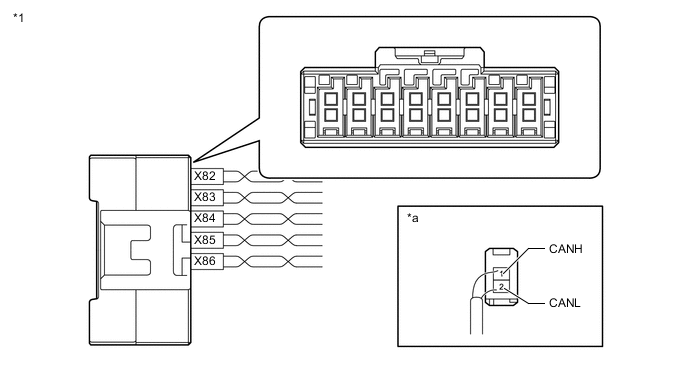
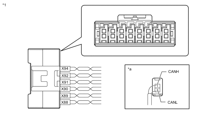
*1 No. 10 CAN Junction Connector - - *a Rear view of wire harness connector
(to No. 10 CAN Junction Connector)
- - Wiring Color Code Color (CANH Side) Color (CANL Side) Connect to X82 P W Front multiplex network door ECU RH X83 G W Position control ECU assembly RH X84 LG W No. 1 headlight ECU sub-assembly RH X85 R W No. 11 CAN junction connector X86 V W Central gateway ECU (network gateway ECU) -
Measure the resistance according to the value(s) in the table below.
Standard Resistance Tester Connection Condition Specified Condition Connected to X82-1 (CANH) - X82-2 (CANL) Cable disconnected from negative (-) battery terminal 200 Ω or higher Front multiplex network door ECU RH X83-1 (CANH) - X83-2 (CANL) Cable disconnected from negative (-) battery terminal 200 Ω or higher Position control ECU assembly RH X84-1 (CANH) - X84-2 (CANL) Cable disconnected from negative (-) battery terminal 200 Ω or higher No. 1 headlight ECU sub-assembly RH X85-1 (CANH) - X85-2 (CANL) Cable disconnected from negative (-) battery terminal 108 to 132 Ω No. 11 CAN junction connector X86-1 (CANH) - X86-2 (CANL) Cable disconnected from negative (-) battery terminal 108 to 132 Ω Central gateway ECU (network gateway ECU) Result Result Proceed to OK A NG (Central gateway ECU [network gateway ECU] CAN main wire) B NG (No. 11 CAN junction connector CAN main wire) C NG (Wire to ECU or sensor) D
A
REPLACE NO. 10 CAN JUNCTION CONNECTOR
B
REPAIR OR REPLACE CAN MAIN WIRE OR CONNECTOR (NO. 10 CAN JUNCTION CONNECTOR - CENTRAL GATEWAY ECU [NETWORK GATEWAY ECU])
D
GO TO STEP 18 Click here
C
-
-
CONNECT CONNECTOR
-
Reconnect the No. 10 CAN junction connectors.
Result Proceed to NEXT
NEXT
-
-
CHECK FOR SHORT IN CAN BUS WIRES (NO. 11 CAN JUNCTION CONNECTOR)
Tech Tips
-
Before disconnecting the connectors, make a note of where it is connected.
-
Reconnect the connector to its original position.
-
Disconnect the No. 11 CAN junction connectors.

*1 No. 11 CAN Junction Connector - - *a Rear view of wire harness connector
(to No. 11 CAN Junction Connector)
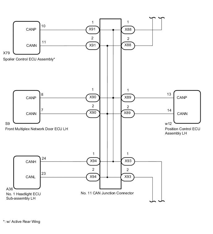
- - Wiring Color Code Color (CANH Side) Color (CANL Side) Connect to X88 R W No. 10 CAN junction connector X89 G W Position control ECU assembly LH X90 P W Front multiplex network door ECU LH X91 GR W Spoiler control ECU assembly* X93 V W No. 1 CAN junction connector X94 LG W No. 1 headlight ECU sub-assembly LH *: w/ Active Rear Wing
-
Measure the resistance according to the value(s) in the table below.
Standard Resistance *: w/ Active Rear WingTester Connection Condition Specified Condition Connected to X88-1 (CANH) - X88-2 (CANL) Cable disconnected from negative (-) battery terminal 108 to 132 Ω No. 10 CAN junction connector X89-1 (CANH) - X89-2 (CANL) Cable disconnected from negative (-) battery terminal 200 Ω or higher Position control ECU assembly LH X90-1 (CANH) - X90-2 (CANL) Cable disconnected from negative (-) battery terminal 200 Ω or higher Front multiplex network door ECU LH X91-1 (CANH) - X91-2 (CANL) Cable disconnected from negative (-) battery terminal 200 Ω or higher Spoiler control ECU assembly* X93-1 (CANH) - X93-2 (CANL) Cable disconnected from negative (-) battery terminal 108 to 132 Ω No. 1 CAN junction connector X94-1 (CANH) - X94-2 (CANL) Cable disconnected from negative (-) battery terminal 200 Ω or higher No. 1 headlight ECU sub-assembly LH
Result Result Proceed to OK A NG (No. 10 CAN junction connector CAN main wire) B NG (No. 1 CAN junction connector CAN main wire) C NG (Wire to ECU or sensor) D
A
REPLACE NO. 11 CAN JUNCTION CONNECTOR
B
REPAIR OR REPLACE CAN MAIN WIRE OR CONNECTOR (NO. 11 CAN JUNCTION CONNECTOR - NO. 10 CAN JUNCTION CONNECTOR)
D
GO TO STEP 18 Click here
C
-
-
CONNECT CONNECTOR
-
Reconnect the No. 11 CAN junction connectors.
Result Proceed to NEXT
NEXT
-
-
CHECK FOR SHORT IN CAN BUS WIRES (NO. 1 CAN JUNCTION CONNECTOR)
-
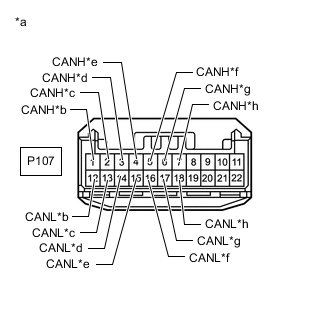
*a Front view of wire harness connector
(to No. 1 CAN Junction Connector)
*b to No. 11 CAN Junction Connector *c to Air Conditioning Amplifier Assembly *d to Meter Mirror Sub-assembly (w/ Headup Display System) *e to Combination Meter Assembly *f to Certification ECU (Smart Key ECU Assembly) *g to Multiplex Tilt and Telescopic ECU *h to Main Body ECU (Multiplex Network Body ECU) Disconnect the No. 1 CAN junction connector.
-
Measure the resistance according to the value(s) in the table below.
Standard Resistance *: w/ Headup Display SystemTester Connection Condition Specified Condition Connected to P107-1 (CANH) - P107-12 (CANL) Cable disconnected from negative (-) battery terminal 108 to 132 Ω No. 11 CAN junction connector P107-2 (CANH) - P107-13 (CANL) Cable disconnected from negative (-) battery terminal 200 Ω or higher Air conditioning amplifier assembly P107-3 (CANH) - P107-14 (CANL) Cable disconnected from negative (-) battery terminal 200 Ω or higher Meter mirror sub-assembly* P107-4 (CANH) - P107-15 (CANL) Cable disconnected from negative (-) battery terminal 108 to 132 Ω Combination meter assembly P107-5 (CANH) - P107-16 (CANL) Cable disconnected from negative (-) battery terminal 200 Ω or higher Certification ECU (smart key ECU assembly) P107-6 (CANH) - P107-17 (CANL) Cable disconnected from negative (-) battery terminal 200 Ω or higher Multiplex tilt and telescopic ECU P107-7 (CANH) - P107-18 (CANL) Cable disconnected from negative (-) battery terminal 200 Ω or higher Main body ECU (multiplex network body ECU)
Result Result Proceed to OK A NG (No. 11 CAN junction connector CAN main wire) B NG (Combination meter assembly CAN main wire) C NG (Wire to ECU or sensor) D
A
REPLACE NO. 1 CAN JUNCTION CONNECTOR
B
REPAIR OR REPLACE CAN MAIN WIRE OR CONNECTOR (NO. 1 CAN JUNCTION CONNECTOR - NO. 11 CAN JUNCTION CONNECTOR)
C
REPAIR OR REPLACE CAN MAIN WIRE OR CONNECTOR (NO. 1 CAN JUNCTION CONNECTOR - COMBINATION METER ASSEMBLY)
D
GO TO STEP 18 Click here
-
-
CONNECT CONNECTOR
-
Reconnect the P25 combination meter assembly connector.
Result Proceed to NEXT
NEXT
-
-
CHECK FOR SHORT IN CAN BUS WIRES (CENTRAL GATEWAY ECU [NETWORK GATEWAY ECU] - NO. 11 CAN JUNCTION CONNECTOR)
-
*a Front view of wire harness connector
(to Central Gateway ECU [Network Gateway ECU])
Disconnect the central gateway ECU (network gateway ECU) connector.
-
Measure the resistance according to the value(s) in the table below.
Standard Resistance Tester Connection Condition Specified Condition P59-15 (CA5H) - P59-16 (CA5L) Cable disconnected from negative (-) battery terminal 108 to 132 Ω Result Result OK NG
OK
REPLACE CENTRAL GATEWAY ECU (NETWORK GATEWAY ECU) Click here
NG
-
-
CONNECT CONNECTOR
-
Reconnect the P59 central gateway ECU (network gateway ECU) connector.
Result Proceed to NEXT
NEXT
-
-
CHECK FOR SHORT IN CAN BUS WIRES (NO. 11 CAN JUNCTION CONNECTOR)
Tech Tips
-
Before disconnecting the connectors, make a note of where it is connected.
-
Reconnect the connector to its original position.
-
Disconnect the No. 11 CAN junction connectors.
*1 No. 11 CAN Junction Connector - - *a Rear view of wire harness connector
(to No. 11 CAN Junction Connector)
- - Wiring Color Code Color (CANH Side) Color (CANL Side) Connect to X88 R W No. 10 CAN junction connector X89 G W Position control ECU assembly LH X90 P W Front multiplex network door ECU LH X91 GR W Spoiler control ECU assembly* X92 V W Central gateway ECU (network gateway ECU) X94 LG W No. 1 headlight ECU sub-assembly LH *: w/ Active Rear Wing
-
Measure the resistance according to the value(s) in the table below.
Standard Resistance *: w/ Active Rear WingTester Connection Condition Specified Condition Connected to X88-1 (CANH) - X88-2 (CANL) Cable disconnected from negative (-) battery terminal 108 to 132 Ω No. 10 CAN junction connector X89-1 (CANH) - X89-2 (CANL) Cable disconnected from negative (-) battery terminal 200 Ω or higher Position control ECU assembly LH X90-1 (CANH) - X90-2 (CANL) Cable disconnected from negative (-) battery terminal 200 Ω or higher Front multiplex network door ECU LH X91-1 (CANH) - X91-2 (CANL) Cable disconnected from negative (-) battery terminal 200 Ω or higher Spoiler control ECU assembly* X92-1 (CANH) - X92-2 (CANL) Cable disconnected from negative (-) battery terminal 108 to 132 Ω Central gateway ECU (network gateway ECU) X94-1 (CANH) - X94-2 (CANL) Cable disconnected from negative (-) battery terminal 200 Ω or higher No. 1 headlight ECU sub-assembly LH
Result Result Proceed to OK A NG (Central gateway ECU [network gateway ECU] CAN main wire) B NG (No. 10 CAN junction connector CAN main wire) C NG (Wire to ECU or sensor) D
A
REPLACE NO. 11 CAN JUNCTION CONNECTOR
B
REPAIR OR REPLACE CAN MAIN WIRE OR CONNECTOR (NO. 11 CAN JUNCTION CONNECTOR - CENTRAL GATEWAY ECU [NETWORK GATEWAY ECU])
D
GO TO STEP 18 Click here
C
-
-
CONNECT CONNECTOR
-
Reconnect the No. 11 CAN junction connectors.
Result Proceed to NEXT
NEXT
-
-
CHECK FOR SHORT IN CAN BUS WIRES (NO. 10 CAN JUNCTION CONNECTOR)
Tech Tips
-
Before disconnecting the connectors, make a note of where it is connected.
-
Reconnect the connector to its original position.
-
Disconnect the No. 10 CAN junction connectors.

*1 No. 10 CAN Junction Connector - - *a Rear view of wire harness connector
(to No. 10 CAN Junction Connector)
- - Wiring Color Code Color (CANH Side) Color (CANL Side) Connect to X82 P W Front multiplex network door ECU RH X83 G W Position control ECU assembly RH X84 LG W No. 1 headlight ECU sub-assembly RH X85 R W No. 11 CAN junction connector X87 V W No. 1 CAN junction connector -
Measure the resistance according to the value(s) in the table below.
Standard Resistance Tester Connection Condition Specified Condition Connected to X82-1 (CANH) - X82-2 (CANL) Cable disconnected from negative (-) battery terminal 200 Ω or higher Front multiplex network door ECU RH X83-1 (CANH) - X83-2 (CANL) Cable disconnected from negative (-) battery terminal 200 Ω or higher Position control ECU assembly RH X84-1 (CANH) - X84-2 (CANL) Cable disconnected from negative (-) battery terminal 200 Ω or higher No. 1 headlight ECU sub-assembly RH X85-1 (CANH) - X85-2 (CANL) Cable disconnected from negative (-) battery terminal 108 to 132 Ω No. 11 CAN junction connector X87-1 (CANH) - X87-2 (CANL) Cable disconnected from negative (-) battery terminal 108 to 132 Ω No. 1 CAN junction connector Result Result Proceed to OK A NG (No. 11 CAN junction connector CAN main wire) B NG (No. 1 CAN junction connector CAN main wire) C NG (Wire to ECU or sensor) D
A
REPLACE NO. 10 CAN JUNCTION CONNECTOR
B
REPAIR OR REPLACE CAN MAIN WIRE OR CONNECTOR (NO. 10 CAN JUNCTION CONNECTOR - NO. 11 CAN JUNCTION CONNECTOR)
D
GO TO STEP 18 Click here
C
-
-
CONNECT CONNECTOR
-
Reconnect the No. 10 CAN junction connectors.
Result Proceed to NEXT
NEXT
-
-
CHECK FOR SHORT IN CAN BUS WIRES (NO. 1 CAN JUNCTION CONNECTOR)
-
Disconnect the No. 1 CAN junction connector.
-
*a Front view of wire harness connector
(to No. 1 CAN Junction Connector)
*b to No. 10 CAN Junction Connector *c to Air Conditioning Amplifier Assembly *d to Meter Mirror Sub-assembly (w/ Headup Display System) *e to Combination Meter Assembly *f to Certification ECU (Smart Key ECU Assembly) *g to Multiplex Tilt and Telescopic ECU *h to Main Body ECU (Multiplex Network Body ECU) Measure the resistance according to the value(s) in the table below.
Standard Resistance *: w/ Headup Display SystemTester Connection Condition Specified Condition Connected to P107-1 (CANH) - P107-12 (CANL) Cable disconnected from negative (-) battery terminal 108 to 132 Ω No. 10 CAN junction connector P107-2 (CANH) - P107-13 (CANL) Cable disconnected from negative (-) battery terminal 200 Ω or higher Air conditioning amplifier assembly P107-3 (CANH) - P107-14 (CANL) Cable disconnected from negative (-) battery terminal 200 Ω or higher Meter mirror sub-assembly* P107-4 (CANH) - P107-15 (CANL) Cable disconnected from negative (-) battery terminal 108 to 132 Ω Combination meter assembly P107-5 (CANH) - P107-16 (CANL) Cable disconnected from negative (-) battery terminal 200 Ω or higher Certification ECU (smart key ECU assembly) P107-6 (CANH) - P107-17 (CANL) Cable disconnected from negative (-) battery terminal 200 Ω or higher Multiplex tilt and telescopic ECU P107-7 (CANH) - P107-18 (CANL) Cable disconnected from negative (-) battery terminal 200 Ω or higher Main body ECU (multiplex network body ECU)
Result Result Proceed to OK A NG (No. 10 CAN junction connector CAN main wire) B NG (Combination meter assembly CAN main wire) C NG (Wire to ECU or sensor) D
A
REPLACE NO. 1 CAN JUNCTION CONNECTOR
B
REPAIR OR REPLACE CAN MAIN WIRE OR CONNECTOR (NO. 1 CAN JUNCTION CONNECTOR - NO. 10 CAN JUNCTION CONNECTOR)
C
REPAIR OR REPLACE CAN MAIN WIRE OR CONNECTOR (NO. 1 CAN JUNCTION CONNECTOR - COMBINATION METER ASSEMBLY)
D
-
-
CHECK FOR SHORT IN CAN BUS WIRES (ECU, SENSOR)
-
*a Component with harness connected
(Central Gateway ECU [Network Gateway ECU])
Reconnect all wire harness connectors.
-
Disconnect the connector that includes terminals CANH and CANL from the ECU or sensor to which the short circuited branch line is connected.
-
Measure the resistance according to the value(s) in the table below.
Standard Resistance Tester Connection Condition Specified Condition P59-15 (CA5H) - P59-16 (CA5L) Cable disconnected from negative (-) battery terminal 54 to 69 Ω Tech Tips
If the resistance becomes normal (between 54 and 69 Ω) when the connector is disconnected from the ECU or sensor, there may be a short in the ECU or sensor.
Result Result OK NG
OK
REPLACE ECU OR SENSOR
NG
REPAIR OR REPLACE HARNESS OR CONNECTOR
-