CAN COMMUNICATION SYSTEM Check Bus 5 Line for Short to +B
DESCRIPTION
There may be a short circuit between one of the CAN bus lines and +B when there is no resistance between terminal 15 (CA5H) of the central gateway ECU (network gateway ECU) and terminal 16 (BAT) of the DLC3, or terminal 16 (CA5L) of the central gateway ECU (network gateway ECU) and terminal 16 (BAT) of the DLC3.
| Symptom | Trouble Area |
|---|---|
| There is no resistance between terminal 15 (CA5H) of the central gateway ECU (network gateway ECU) and terminal 16 (BAT) of the DLC3, or terminal 16 (CA5L) of the central gateway ECU (network gateway ECU) and terminal 16 (BAT) of the DLC3. |
|
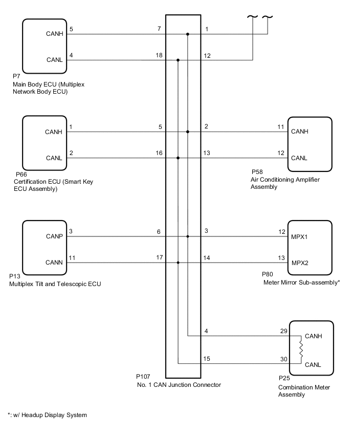
*2: w/ Headup Display System
WIRING DIAGRAM
-
for LHD
-
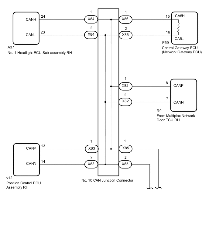
for RHD
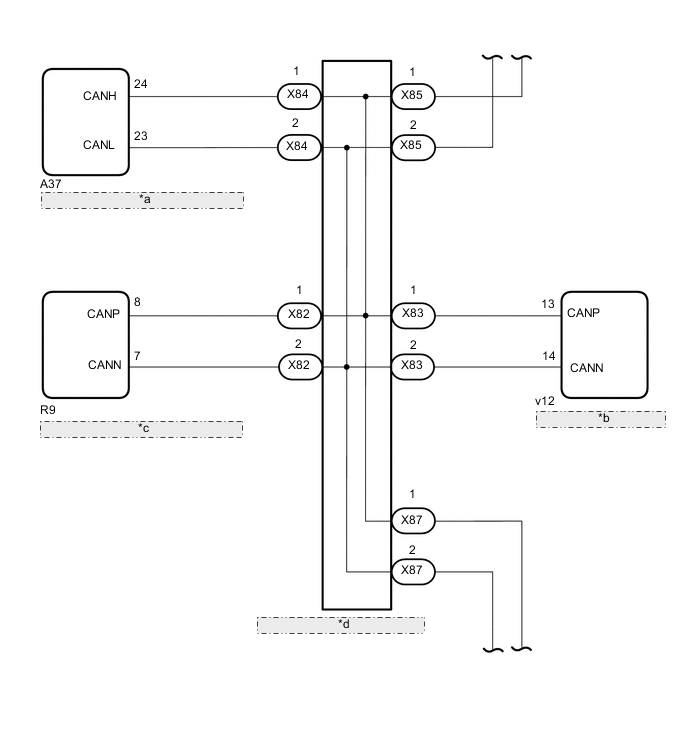
*a No. 1 Headlight ECU Sub-assembly RH *b Position Control ECU Assembly RH *c Front Multiplex Network Door ECU RH *d No. 10 CAN Junction Connector
CAUTION / NOTICE / HINT
CAUTION:
When performing the confirmation driving pattern, obey all speed limits and traffic laws.
Note
-
Because the order of diagnosis is important to allow correct diagnosis, make sure to begin troubleshooting using How to Proceed with Troubleshooting when CAN communication system related DTCs are output.
-
Before measuring the resistance of the CAN bus, turn the engine switch off and leave the vehicle for 1 minute or more without operating the key or any switches, or opening or closing the doors. After that, disconnect the cable from the negative (-) battery terminal and leave the vehicle for 1 minute or more before measuring the resistance.
-
After turning the engine switch off, waiting time may be required before disconnecting the cable from the negative (-) battery terminal. Therefore, make sure to read the disconnecting the cable from the negative (-) battery terminal notices before proceeding with work.
-
Some parts must be initialized and set when replacing or removing and installing parts.
-
After performing repairs, perform the DTC check procedure and confirm that the DTCs are not output again.
DTC check procedure: Turn the engine switch on (IG) and wait for 1 minute or more. Then operate the suspected malfunctioning system and drive the vehicle at 60 km/h (37 mph) or more for 5 minutes or more.
-
After the repair, perform the CAN bus check and check that all the ECUs and sensors connected to the CAN communication system are displayed as normal.
-
When replacing the combination meter assembly, always replace it with a new one. If a combination meter assembly which was installed to another vehicle is used, the information stored in it will not match the information from the vehicle and a DTC may be stored.
-
Before replacing the certification ECU (smart key ECU assembly), refer to the entry and start system.
Tech Tips
-
Before disconnecting related connectors for inspection, push in on each connector body to check that the connector is not loose or disconnected.
-
When a connector is disconnected, check that the terminals and connector body are not cracked, deformed or corroded.
PROCEDURE
-
CHECK VEHICLE TYPE
-
Check vehicle type.
Result Result Proceed to for LHD A for RHD B
B 
CHECK FOR SHORT TO B+ IN CAN BUS WIRE (NO. 11 CAN JUNCTION CONNECTOR) Click here
A 
-
-
CHECK FOR SHORT TO B+ IN CAN BUS WIRE (NO. 10 CAN JUNCTION CONNECTOR)
Tech Tips
-
Before disconnecting the connectors, make a note of where it is connected.
-
Reconnect the connector to its original position.
-
Disconnect the cable from the negative (-) battery terminal.
-
Disconnect the No. 10 CAN junction connectors.

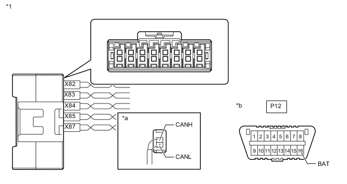
*1 No. 10 CAN Junction Connector - - *a Rear view of wire harness connector
(to No. 10 CAN Junction Connector)
*b Front view of DLC3 Wiring Color Code Color (CANH Side) Color (CANL Side) Connect to X82 P W Front multiplex network door ECU RH X83 G W Position control ECU assembly RH X84 LG W No. 1 headlight ECU sub-assembly RH X85 R W No. 11 CAN junction connector X86 V W Central gateway ECU (network gateway ECU) -
Measure the resistance according to the value(s) in the table below.
Standard Resistance Tester Connection Condition Specified Condition Connected to X82-1 (CANH) - P12-16 (BAT) Cable disconnected from negative (-) battery terminal 6 kΩ or higher Front multiplex network door ECU RH X82-2 (CANL) - P12-16 (BAT) X83-1 (CANH) - P12-16 (BAT) Cable disconnected from negative (-) battery terminal 6 kΩ or higher Position control ECU assembly RH X83-2 (CANL) - P12-16 (BAT) X84-1 (CANH) - P12-16 (BAT) Cable disconnected from negative (-) battery terminal 6 kΩ or higher No. 1 headlight ECU sub-assembly RH X84-2 (CANL) - P12-16 (BAT) X85-1 (CANH) - P12-16 (BAT) Cable disconnected from negative (-) battery terminal 6 kΩ or higher No. 11 CAN junction connector X85-2 (CANL) - P12-16 (BAT) X86-1 (CANH) - P12-16 (BAT) Cable disconnected from negative (-) battery terminal 6 kΩ or higher Central gateway ECU (network gateway ECU) X86-2 (CANL) - P12-16 (BAT) Result Result Proceed to OK A NG (Central gateway ECU [network gateway ECU] CAN main wire) B NG (No. 11 CAN junction connector CAN main wire) C NG (Wire to ECU or sensor) D
A 
REPLACE NO. 10 CAN JUNCTION CONNECTOR
C
CONNECT CONNECTOR Click here
D
GO TO STEP 16 Click here
B
-
-
CONNECT CONNECTOR
-
Reconnect the No. 10 CAN junction connectors.
Result Proceed to NEXT
NEXT
-
-
CHECK FOR SHORT TO B+ IN CAN BUS WIRE (CENTRAL GATEWAY ECU [NETWORK GATEWAY ECU] - NO. 10 CAN JUNCTION CONNECTOR)
-
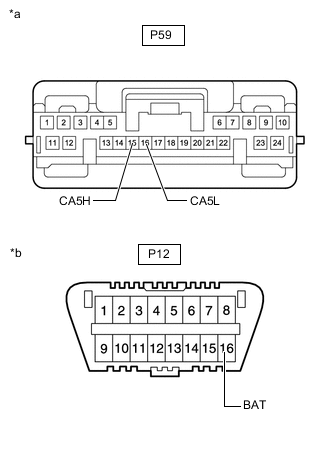
*a Front view of wire harness connector
(to Central Gateway ECU [Network Gateway ECU])
*b Front view of DLC3 Disconnect the central gateway ECU (network gateway ECU) connector.
-
Measure the resistance according to the value(s) in the table below.
Standard Resistance Tester Connection Condition Specified Condition P59-15 (CA5H) - P12-16 (BAT) Cable disconnected from negative (-) battery terminal 6 kΩ or higher P59-16 (CA5L) - P12-16 (BAT) Result Result OK NG
OK
REPLACE CENTRAL GATEWAY ECU (NETWORK GATEWAY ECU) Click here
NG
REPAIR OR REPLACE CAN MAIN WIRE OR CONNECTOR (CENTRAL GATEWAY ECU [NETWORK GATEWAY ECU] - NO. 10 CAN JUNCTION CONNECTOR)
-
-
CONNECT CONNECTOR
-
Reconnect the No. 10 CAN junction connectors.
Result Proceed to NEXT
NEXT
-
-
CHECK FOR SHORT TO B+ IN CAN BUS WIRE (NO. 11 CAN JUNCTION CONNECTOR)
Tech Tips
-
Before disconnecting the connectors, make a note of where it is connected.
-
Reconnect the connector to its original position.
-
Disconnect the No. 11 CAN junction connectors.
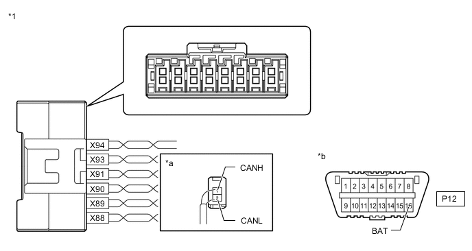
*1 No. 11 CAN Junction Connector - - *a Rear view of wire harness connector
(to No. 11 CAN Junction Connector)
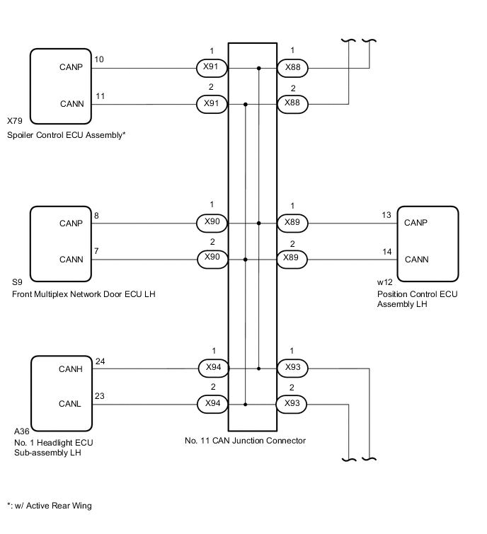
*b Front view of DLC3 Wiring Color Code Color (CANH Side) Color (CANL Side) Connect to X88 R W No. 10 CAN junction connector X89 G W Position control ECU assembly LH X90 P W Front multiplex network door ECU LH X91 GR W Spoiler control ECU assembly* X93 V W No. 1 CAN junction connector X94 LG W No. 1 headlight ECU sub-assembly LH *: w/ Active Rear Wing
-
Measure the resistance according to the value(s) in the table below.
Standard Resistance *: w/ Active Rear WingTester Connection Condition Specified Condition Connected to X88-1 (CANH) - P12-16 (BAT) Cable disconnected from negative (-) battery terminal 6 kΩ or higher No. 10 CAN junction connector X88-2 (CANL) - P12-16 (BAT) X89-1 (CANH) - P12-16 (BAT) Cable disconnected from negative (-) battery terminal 6 kΩ or higher Position control ECU assembly LH X89-2 (CANL) - P12-16 (BAT) X90-1 (CANH) - P12-16 (BAT) Cable disconnected from negative (-) battery terminal 6 kΩ or higher Front multiplex network door ECU LH X90-2 (CANL) - P12-16 (BAT) X91-1 (CANH) - P12-16 (BAT) Cable disconnected from negative (-) battery terminal 6 kΩ or higher Spoiler control ECU assembly* X91-2 (CANL) - P12-16 (BAT) X93-1 (CANH) - P12-16 (BAT) Cable disconnected from negative (-) battery terminal 6 kΩ or higher No. 1 CAN junction connector X93-2 (CANL) - P12-16 (BAT) X94-1 (CANH) - P12-16 (BAT) Cable disconnected from negative (-) battery terminal 6 kΩ or higher No. 1 headlight ECU sub-assembly LH X94-2 (CANL) - P12-16 (BAT)
Result Result Proceed to OK A NG (No. 10 CAN junction connector CAN main wire) B NG (No. 1 CAN junction connector CAN main wire) C NG (Wire to ECU or sensor) D
A
REPLACE NO. 11 CAN JUNCTION CONNECTOR
B
REPAIR OR REPLACE CAN MAIN WIRE OR CONNECTOR (NO. 11 CAN JUNCTION CONNECTOR - NO. 10 CAN JUNCTION CONNECTOR)
D
GO TO STEP 16 Click here
C
-
-
CONNECT CONNECTOR
-
Reconnect the No. 11 CAN junction connectors.
Result Proceed to NEXT
NEXT
-
-
CHECK FOR SHORT TO B+ IN CAN BUS WIRE (NO. 1 CAN JUNCTION CONNECTOR)
-
Disconnect the No. 1 CAN junction connector.
-
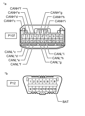
*a Front view of wire harness connector
(to No. 1 CAN Junction Connector)
*b Front view of DLC3 *c to No. 11 CAN Junction Connector *d to Air Conditioning Amplifier Assembly *e to Meter Mirror Sub-assembly (w/ Headup Display System) *f to Combination Meter Assembly *g to Certification ECU (Smart Key ECU Assembly) *h to Multiplex Tilt and Telescopic ECU *i to Main Body ECU (Multiplex Network Body ECU) Measure the resistance according to the value(s) in the table below.
Standard Resistance *: w/ Headup Display SystemTester Connection Condition Specified Condition Connected to P107-1 (CANH) - P12-16 (BAT) Cable disconnected from negative (-) battery terminal 6 kΩ or higher No. 11 CAN junction connector P107-12 (CANL) - P12-16 (BAT) P107-2 (CANH) - P12-16 (BAT) Cable disconnected from negative (-) battery terminal 6 kΩ or higher Air conditioning amplifier assembly P107-13 (CANL) - P12-16 (BAT) P107-3 (CANH) - P12-16 (BAT) Cable disconnected from negative (-) battery terminal 6 kΩ or higher Meter mirror sub-assembly* P107-14 (CANL) - P12-16 (BAT) P107-4 (CANH) - P12-16 (BAT) Cable disconnected from negative (-) battery terminal 6 kΩ or higher Combination meter assembly P107-15 (CANL) - P12-16 (BAT) P107-5 (CANH) - P12-16 (BAT) Cable disconnected from negative (-) battery terminal 6 kΩ or higher Certification ECU (smart key ECU assembly) P107-16 (CANL) - P12-16 (BAT) P107-6 (CANH) - P12-16 (BAT) Cable disconnected from negative (-) battery terminal 6 kΩ or higher Multiplex tilt and telescopic ECU P107-17 (CANL) - P12-16 (BAT) P107-7 (CANH) - P12-16 (BAT) Cable disconnected from negative (-) battery terminal 6 kΩ or higher Main body ECU (multiplex network body ECU) P107-18 (CANL) - P12-16 (BAT)
Result Result Proceed to OK A NG (No. 11 CAN junction connector CAN main wire) B NG (Wire to ECU or sensor) C
A
REPLACE NO. 1 CAN JUNCTION CONNECTOR
B
REPAIR OR REPLACE CAN MAIN WIRE OR CONNECTOR (NO. 1 CAN JUNCTION CONNECTOR - NO. 11 CAN JUNCTION CONNECTOR)
C
GO TO STEP 16 Click here
-
-
CHECK FOR SHORT TO B+ IN CAN BUS WIRE (NO. 11 CAN JUNCTION CONNECTOR)
Tech Tips
-
Before disconnecting the connectors, make a note of where it is connected.
-
Reconnect the connector to its original position.
-
Disconnect the cable from the negative (-) battery terminal.
-
Disconnect the No. 11 CAN junction connectors.

*1 No. 11 CAN Junction Connector - - *a Rear view of wire harness connector
(to No. 11 CAN Junction Connector)
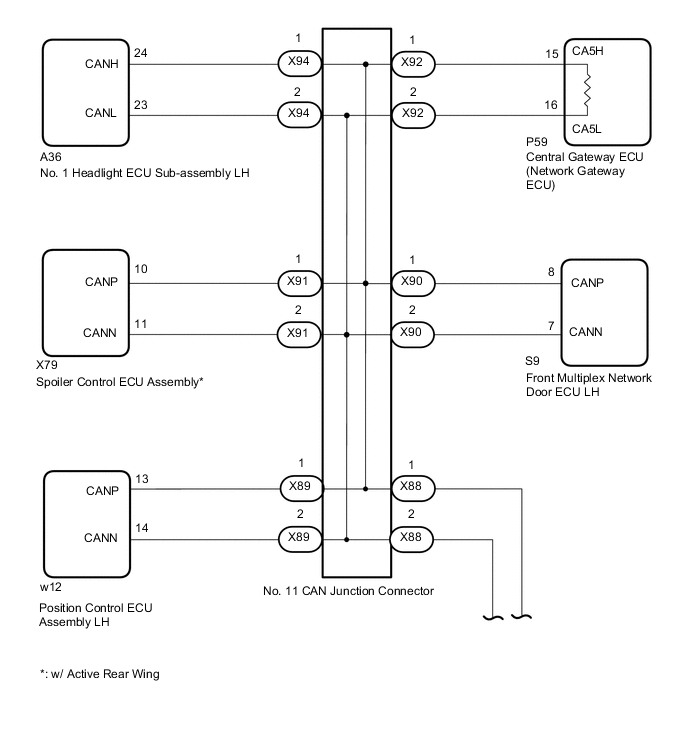
*b Front view of DLC3 Wiring Color Code Color (CANH Side) Color (CANL Side) Connect to X88 R W No. 10 CAN junction connector X89 G W Position control ECU assembly LH X90 P W Front multiplex network door ECU LH X91 GR W Spoiler control ECU assembly* X92 V W Central gateway ECU (network gateway ECU) X94 LG W No. 1 headlight ECU sub-assembly LH *: w/ Active Rear Wing
-
Measure the resistance according to the value(s) in the table below.
Standard Resistance *: w/ Active Rear WingTester Connection Condition Specified Condition Connected to X88-1 (CANH) - P12-16 (BAT) Cable disconnected from negative (-) battery terminal 6 kΩ or higher No. 10 CAN junction connector X88-2 (CANL) - P12-16 (BAT) X89-1 (CANH) - P12-16 (BAT) Cable disconnected from negative (-) battery terminal 6 kΩ or higher Position control ECU assembly LH X89-2 (CANL) - P12-16 (BAT) X90-1 (CANH) - P12-16 (BAT) Cable disconnected from negative (-) battery terminal 6 kΩ or higher Front multiplex network door ECU LH X90-2 (CANL) - P12-16 (BAT) X91-1 (CANH) - P12-16 (BAT) Cable disconnected from negative (-) battery terminal 6 kΩ or higher Spoiler control ECU assembly* X91-2 (CANL) - P12-16 (BAT) X92-1 (CANH) - P12-16 (BAT) Cable disconnected from negative (-) battery terminal 6 kΩ or higher Central gateway ECU (network gateway ECU) X92-2 (CANL) - P12-16 (BAT) X94-1 (CANH) - P12-16 (BAT) Cable disconnected from negative (-) battery terminal 6 kΩ or higher No. 1 headlight ECU sub-assembly LH X94-2 (CANL) - P12-16 (BAT)
Result Result Proceed to OK A NG (Central gateway ECU [network gateway ECU] CAN main wire) B NG (No. 10 CAN junction connector CAN main wire) C NG (Wire to ECU or sensor) D
A
REPLACE NO. 11 CAN JUNCTION CONNECTOR
C
CONNECT CONNECTOR Click here
D
GO TO STEP 16 Click here
B
-
-
CONNECT CONNECTOR
-
Reconnect the No. 11 CAN junction connectors.
Result Proceed to NEXT
NEXT
-
-
CHECK FOR SHORT TO B+ IN CAN BUS WIRE (CENTRAL GATEWAY ECU [NETWORK GATEWAY ECU] - NO. 11 CAN JUNCTION CONNECTOR)
-
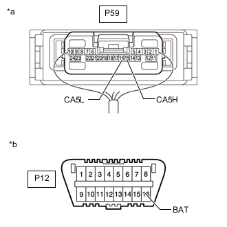
*a Front view of wire harness connector
(to Central Gateway ECU [Network Gateway ECU])
*b Front view of DLC3 Disconnect the central gateway ECU (network gateway ECU) connector.
-
Measure the resistance according to the value(s) in the table below.
Standard Resistance Tester Connection Condition Specified Condition P59-15 (CA5H) - P12-16 (BAT) Cable disconnected from negative (-) battery terminal 6 kΩ or higher P59-16 (CA5L) - P12-16 (BAT) Result Result OK NG
OK
REPLACE CENTRAL GATEWAY ECU (NETWORK GATEWAY ECU) Click here
NG
REPAIR OR REPLACE CAN MAIN WIRE OR CONNECTOR (CENTRAL GATEWAY ECU [NETWORK GATEWAY ECU] - NO. 11 CAN JUNCTION CONNECTOR)
-
-
CONNECT CONNECTOR
-
Reconnect the No. 11 CAN junction connectors.
Result Proceed to NEXT
NEXT
-
-
CHECK FOR SHORT TO B+ IN CAN BUS WIRE (NO. 10 CAN JUNCTION CONNECTOR)
Tech Tips
-
Before disconnecting the connectors, make a note of where it is connected.
-
Reconnect the connector to its original position.
-
Disconnect the No. 10 CAN junction connectors.
*1 No. 10 CAN Junction Connector - - *a Rear view of wire harness connector
(to No. 10 CAN Junction Connector)
*b Front view of DLC3 Wiring Color Code Color (CANH Side) Color (CANL Side) Connect to X82 P W Front multiplex network door ECU RH X83 G W Position control ECU assembly RH X84 LG W No. 1 headlight ECU sub-assembly RH X85 R W No. 11 CAN junction connector X87 V W No. 1 CAN junction connector -
Measure the resistance according to the value(s) in the table below.
Standard Resistance Tester Connection Condition Specified Condition Connected to X82-1 (CANH) - P12-16 (BAT) Cable disconnected from negative (-) battery terminal 6 kΩ or higher Front multiplex network door ECU RH X82-2 (CANL) - P12-16 (BAT) X83-1 (CANH) - P12-16 (BAT) Cable disconnected from negative (-) battery terminal 6 kΩ or higher Position control ECU assembly RH X83-2 (CANL) - P12-16 (BAT) X84-1 (CANH) - P12-16 (BAT) Cable disconnected from negative (-) battery terminal 6 kΩ or higher No. 1 headlight ECU sub-assembly RH X84-2 (CANL) - P12-16 (BAT) X85-1 (CANH) - P12-16 (BAT) Cable disconnected from negative (-) battery terminal 6 kΩ or higher No. 11 CAN junction connector X85-2 (CANL) - P12-16 (BAT) X87-1 (CANH) - P12-16 (BAT) Cable disconnected from negative (-) battery terminal 6 kΩ or higher No. 1 CAN junction connector X87-2 (CANL) - P12-16 (BAT) Result Result Proceed to OK A NG (No. 11 CAN junction connector CAN main wire) B NG (No. 1 CAN junction connector CAN main wire) C NG (Wire to ECU or sensor) D
A
REPLACE NO. 10 CAN JUNCTION CONNECTOR
B
REPAIR OR REPLACE CAN MAIN WIRE OR CONNECTOR (NO. 10 CAN JUNCTION CONNECTOR - NO. 11 CAN JUNCTION CONNECTOR)
D
GO TO STEP 16 Click here
C
-
-
CONNECT CONNECTOR
-
Reconnect the No. 10 CAN junction connectors.
Result Proceed to NEXT
NEXT
-
-
CHECK FOR SHORT TO B+ IN CAN BUS WIRE (NO. 1 CAN JUNCTION CONNECTOR)
-
*a Front view of wire harness connector
(to No. 1 CAN Junction Connector)
*b Front view of DLC3 *c to No. 10 CAN Junction Connector *d to Air Conditioning Amplifier Assembly *e to Meter Mirror Sub-assembly (w/ Headup Display System) *f to Combination Meter Assembly *g to Certification ECU (Smart Key ECU Assembly) *h to Multiplex Tilt and Telescopic ECU *i to Main Body ECU (Multiplex Network Body ECU) Disconnect the No. 1 CAN junction connector.
-
Measure the resistance according to the value(s) in the table below.
Standard Resistance *: w/ Headup Display SystemTester Connection Condition Specified Condition Connected to P107-1 (CANH) - P12-16 (BAT) Cable disconnected from negative (-) battery terminal 6 kΩ or higher No. 10 CAN junction connector P107-12 (CANL) - P12-16 (BAT) P107-2 (CANH) - P12-16 (BAT) Cable disconnected from negative (-) battery terminal 6 kΩ or higher Air conditioning amplifier assembly P107-13 (CANL) - P12-16 (BAT) P107-3 (CANH) - P12-16 (BAT) Cable disconnected from negative (-) battery terminal 6 kΩ or higher Meter mirror sub-assembly* P107-14 (CANL) - P12-16 (BAT) P107-4 (CANH) - P12-16 (BAT) Cable disconnected from negative (-) battery terminal 6 kΩ or higher Combination meter assembly P107-15 (CANL) - P12-16 (BAT) P107-5 (CANH) - P12-16 (BAT) Cable disconnected from negative (-) battery terminal 6 kΩ or higher Certification ECU (smart key ECU assembly) P107-16 (CANL) - P12-16 (BAT) P107-6 (CANH) - P12-16 (BAT) Cable disconnected from negative (-) battery terminal 6 kΩ or higher Multiplex tilt and telescopic ECU P107-17 (CANL) - P12-16 (BAT) P107-7 (CANH) - P12-16 (BAT) Cable disconnected from negative (-) battery terminal 6 kΩ or higher Main body ECU (multiplex network body ECU) P107-18 (CANL) - P12-16 (BAT)
Result Result Proceed to OK A NG (No. 10 CAN junction connector CAN main wire) B NG (Wire to ECU or sensor) C
A
REPLACE NO. 1 CAN JUNCTION CONNECTOR
B
REPAIR OR REPLACE CAN MAIN WIRE OR CONNECTOR (NO. 1 CAN JUNCTION CONNECTOR - NO. 10 CAN JUNCTION CONNECTOR)
C
-
-
CHECK FOR SHORT TO B+ IN CAN BUS WIRE (ECU, SENSOR)
-
*a Component with harness connected
(Central Gateway ECU [Network Gateway ECU])
*b Front view of DLC3 Reconnect all wire harness connectors.
-
Disconnect the connector that includes terminals CANH and CANL from the ECU or sensor to which the bus line shorted to +B is connected.
-
Measure the resistance according to the value(s) in the table below.
Standard Resistance Tester Connection Condition Specified Condition P59-15 (CA5H) - P12-16 (BAT) Cable disconnected from negative (-) battery terminal 6 kΩ or higher P59-16 (CA5L) - P12-16 (BAT) Tech Tips
-
If the resistance changes to 6 kΩ or higher when the connector is disconnected from the ECU or sensor, there may be a short in the ECU or sensor.
-
If the resistance does not become normal when the connector is disconnected from the ECU or sensor, check for a short to +B in the wire harness and repair or replace the wire harness or connector if necessary.
Result Result OK NG -
OK
REPLACE ECU OR SENSOR
NG
REPAIR OR REPLACE HARNESS OR CONNECTOR
-