CAN COMMUNICATION SYSTEM Check Bus 4 Lines for Short Circuit
DESCRIPTION
There may be a short circuit between the CAN main bus lines and/or CAN branch lines when the resistance between terminals 22 (CA2H) and 7 (CA2L) of the central gateway ECU (network gateway ECU) is below 54 Ω.
| Symptom | Trouble Area |
|---|---|
| Resistance between terminals 22 (CA2H) and 7 (CA2L) of the central gateway ECU (network gateway ECU) is below 54 Ω. |
|
*2: w/ Variable Gear Ratio Steering System
WIRING DIAGRAM
CAUTION / NOTICE / HINT
CAUTION:
When performing the confirmation driving pattern, obey all speed limits and traffic laws.
Note
-
Because the order of diagnosis is important to allow correct diagnosis, make sure to begin troubleshooting using How to Proceed with Troubleshooting when CAN communication system related DTCs are output.
-
Before measuring the resistance of the CAN bus, turn the engine switch off and leave the vehicle for 1 minute or more without operating the key or any switches, or opening or closing the doors. After that, disconnect the cable from the negative (-) battery terminal and leave the vehicle for 1 minute or more before measuring the resistance.
-
After turning the engine switch off, waiting time may be required before disconnecting the cable from the negative (-) battery terminal. Therefore, make sure to read the disconnecting the cable from the negative (-) battery terminal notices before proceeding with work.
-
Some parts must be initialized and set when replacing or removing and installing parts.
-
After performing repairs, perform the DTC check procedure and confirm that the DTCs are not output again.
DTC check procedure: Turn the engine switch on (IG) and wait for 1 minute or more. Then operate the suspected malfunctioning system and drive the vehicle at 60 km/h (37 mph) or more for 5 minutes or more.
-
After the repair, perform the CAN bus check and check that all the ECUs and sensors connected to the CAN communication system are displayed as normal.
Tech Tips
-
Before disconnecting related connectors for inspection, push in on each connector body to check that the connector is not loose or disconnected.
-
When a connector is disconnected, check that the terminals and connector body are not cracked, deformed or corroded.
PROCEDURE
-
CHECK FOR SHORT IN CAN BUS WIRES (NO. 3 CAN JUNCTION TERMINAL - NO. 13 CAN JUNCTION CONNECTOR)
-
Disconnect the cable from the negative (-) battery terminal.
-
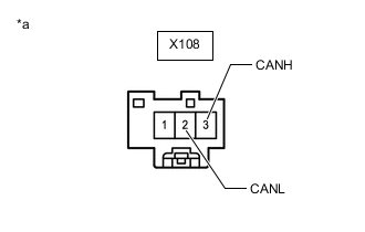
*a Front view of wire harness connector
(to No. 3 CAN Junction Terminal)
Disconnect the No. 3 CAN junction terminal connector.
-
Measure the resistance according to the value(s) in the table below.
Standard Resistance Tester Connection Condition Specified Condition X108-3 (CANH) - X108-2 (CANL) Cable disconnected from negative (-) battery terminal 108 to 132 Ω Result Result OK NG
OK 
REPLACE NO. 3 CAN JUNCTION TERMINAL
NG 
-
-
CONNECT CONNECTOR
-
Reconnect the X108 No. 3 CAN junction terminal connector.
Result Proceed to NEXT
NEXT
-
-
CHECK FOR SHORT IN CAN BUS WIRES (NO. 2 CAN JUNCTION TERMINAL - NO. 12 CAN JUNCTION CONNECTOR)
-
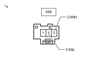
*a Front view of wire harness connector
(to No. 2 CAN Junction Terminal)
Disconnect the No. 2 CAN junction terminal connector.
-
Measure the resistance according to the value(s) in the table below.
Standard Resistance Tester Connection Condition Specified Condition X98-3 (CANH) - X98-2 (CANL) Cable disconnected from negative (-) battery terminal 108 to 132 Ω Result Result Proceed to OK A NG (for LHD) B NG (for RHD) C
A
REPLACE NO. 2 CAN JUNCTION TERMINAL
C 
CONNECT CONNECTOR Click here
B
-
-
CONNECT CONNECTOR
-
Reconnect the X98 No. 2 CAN junction terminal connector.
Result Proceed to NEXT
NEXT
-
-
CHECK FOR SHORT IN CAN BUS WIRES (CENTRAL GATEWAY ECU [NETWORK GATEWAY ECU] - NO. 12 CAN JUNCTION CONNECTOR)
-
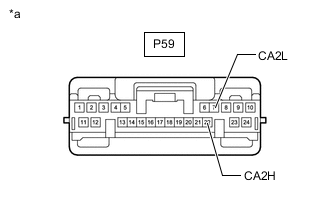
*a Front view of wire harness connector
(to Central Gateway ECU [Network Gateway ECU])
Disconnect the central gateway ECU (network gateway ECU) connector.
-
Measure the resistance according to the value(s) in the table below.
Standard Resistance Tester Connection Condition Specified Condition P59-22 (CA2H) - P59-7 (CA2L) Cable disconnected from negative (-) battery terminal 54 to 69 Ω Result Result OK NG
OK
REPLACE CENTRAL GATEWAY ECU (NETWORK GATEWAY ECU) Click here
NG
-
-
CONNECT CONNECTOR
-
Reconnect the P59 central gateway ECU (network gateway ECU) connector.
Result Proceed to NEXT
NEXT
-
-
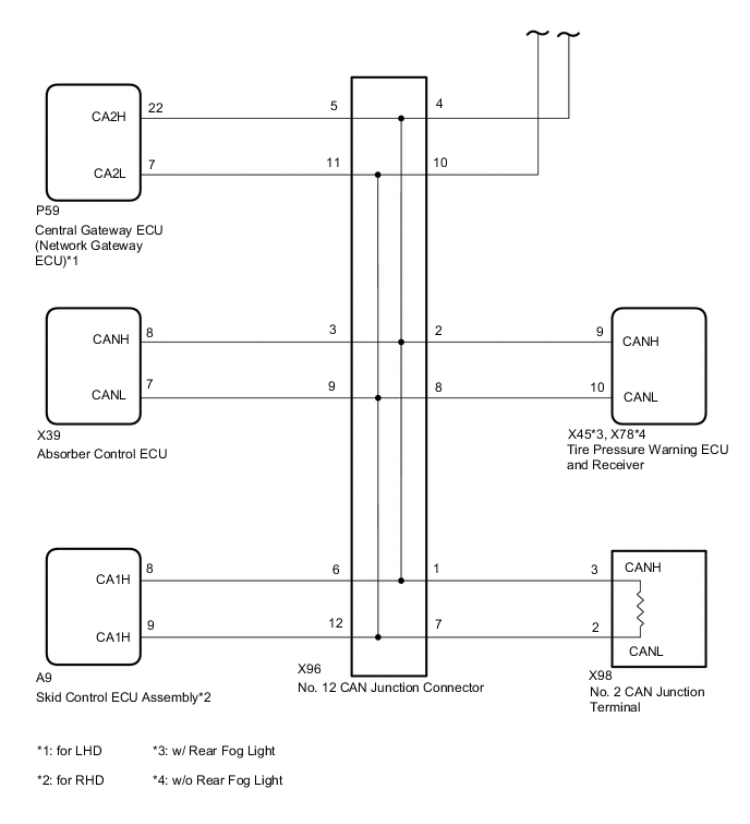
CHECK FOR SHORT IN CAN BUS WIRES (NO. 12 CAN JUNCTION CONNECTOR)
-
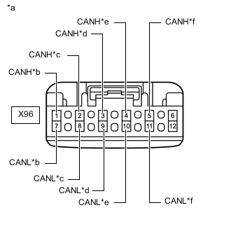
*a Front view of wire harness connector
(to No. 12 CAN Junction Connector)
*b to No. 2 CAN Junction Terminal *c to Tire Pressure Warning ECU and Receiver *d to Absorber Control ECU *e to No. 2 CAN Junction Connector *f to Central Gateway ECU (Network Gateway ECU) Disconnect the No. 12 CAN junction connector.
-
Measure the resistance according to the value(s) in the table below.
Standard Resistance Tester Connection Condition Specified Condition Connected to X96-1 (CANH) - X96-7 (CANL) Cable disconnected from negative (-) battery terminal 108 to 132 Ω No. 2 CAN junction terminal X96-2 (CANH) - X96-8 (CANL) Cable disconnected from negative (-) battery terminal 200 Ω or higher Tire pressure warning ECU and receiver X96-3 (CANH) - X96-9 (CANL) Cable disconnected from negative (-) battery terminal 200 Ω or higher Absorber control ECU X96-4 (CANH) - X96-10 (CANL) Cable disconnected from negative (-) battery terminal 108 to 132 Ω No. 2 CAN junction connector X96-5 (CANH) - X96-11 (CANL) Cable disconnected from negative (-) battery terminal 200 Ω or higher Central gateway ECU (network gateway ECU) Result Result Proceed to OK A NG (No. 2 CAN junction terminal CAN main wire) B NG (Central gateway ECU [network gateway ECU] CAN branch wire) C NG (No. 2 CAN junction connector CAN main wire) D NG (Wire to ECU or sensor) E
A
REPLACE NO. 12 CAN JUNCTION CONNECTOR
B
REPAIR OR REPLACE CAN MAIN WIRE OR CONNECTOR (NO. 12 CAN JUNCTION CONNECTOR - NO. 2 CAN JUNCTION TERMINAL)
C
REPAIR OR REPLACE CAN BRANCH WIRE OR CONNECTOR (NO. 12 CAN JUNCTION CONNECTOR - CENTRAL GATEWAY ECU [NETWORK GATEWAY ECU])
E
GO TO STEP 20 Click here
D
-
-
CONNECT CONNECTOR
-
Reconnect the X96 No. 12 CAN junction connector.
Result Proceed to NEXT
NEXT
-
-
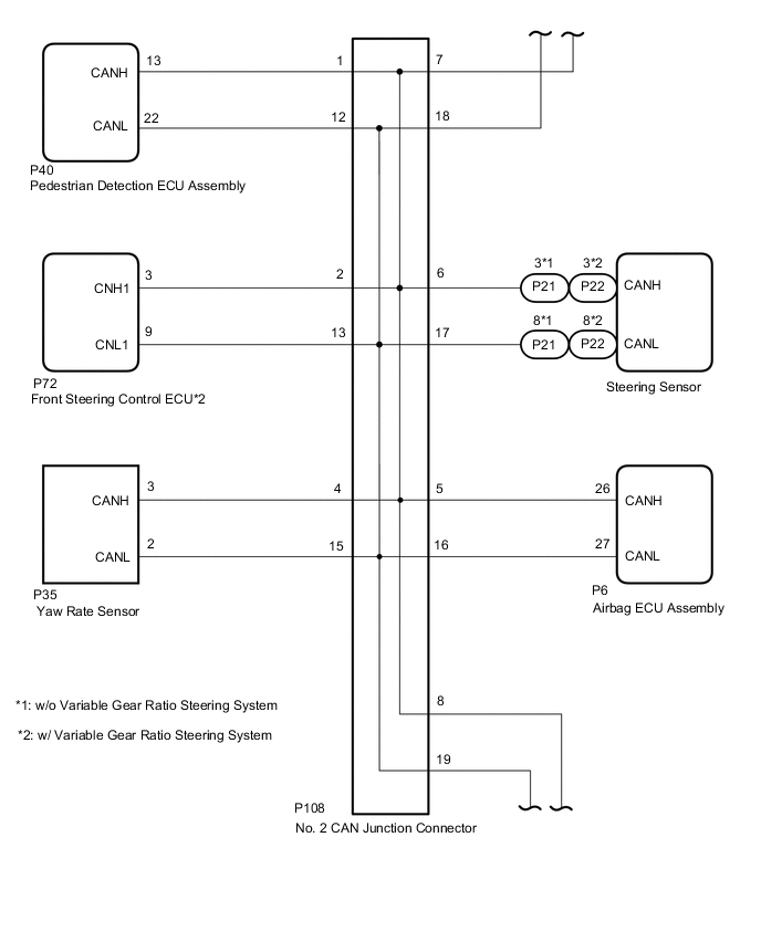
CHECK FOR SHORT IN CAN BUS WIRES (NO. 2 CAN JUNCTION CONNECTOR)
-
Disconnect the No. 2 CAN junction connector.

*a Front view of wire harness connector
(to No. 2 CAN Junction Connector)
*b to Pedestrian Detection ECU Assembly *c to Front Steering Control ECU (w/ Variable Gear Ratio Steering System) *d to Yaw Rate Sensor *e to Airbag ECU Assembly *f to Steering Sensor *g to No. 13 CAN Junction Connector *h to No. 12 CAN Junction Connector -
Measure the resistance according to the value(s) in the table below.
Standard Resistance *: w/ Variable Gear Ratio Steering SystemTester Connection Condition Specified Condition Connected to P108-1 (CANH) - P108-12 (CANL) Cable disconnected from negative (-) battery terminal 200 Ω or higher Pedestrian detection ECU assembly P108-2 (CANH) - P108-13 (CANL) Cable disconnected from negative (-) battery terminal 200 Ω or higher Front steering control ECU* P108-4 (CANH) - P108-15 (CANL) Cable disconnected from negative (-) battery terminal 200 Ω or higher Yaw rate sensor P108-5 (CANH) - P108-16 (CANL) Cable disconnected from negative (-) battery terminal 200 Ω or higher Airbag ECU assembly P108-6 (CANH) - P108-17 (CANL) Cable disconnected from negative (-) battery terminal 200 Ω or higher Steering sensor P108-7 (CANH) - P108-18 (CANL) Cable disconnected from negative (-) battery terminal 108 to 132 Ω No. 13 CAN junction connector P108-8 (CANH) - P108-19 (CANL) Cable disconnected from negative (-) battery terminal 108 to 132 Ω No. 12 CAN junction connector
Result Result Proceed to OK A NG (No. 12 CAN junction connector CAN main wire) B NG (No. 13 CAN junction connector CAN main wire) C NG (Wire to ECU or sensor) D
A
REPLACE NO. 2 CAN JUNCTION CONNECTOR
B
REPAIR OR REPLACE CAN MAIN WIRE OR CONNECTOR (NO. 2 CAN JUNCTION CONNECTOR - NO. 12 CAN JUNCTION CONNECTOR)
D
GO TO STEP 20 Click here
C
-
-
CONNECT CONNECTOR
-
Reconnect the P108 No. 2 CAN junction connector.
Result Proceed to NEXT
NEXT
-
-
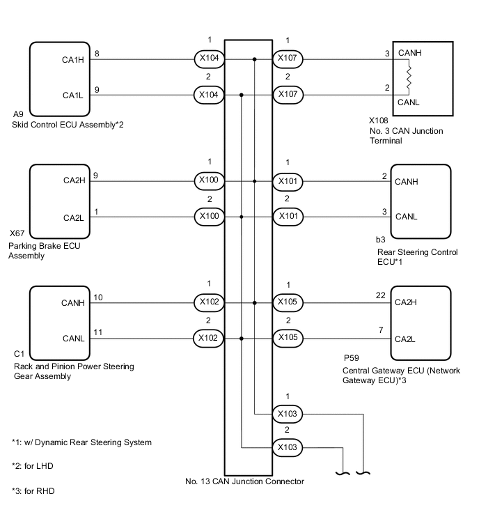
CHECK FOR SHORT IN CAN BUS WIRES (NO. 13 CAN JUNCTION CONNECTOR)
Tech Tips
-
Before disconnecting the connectors, make a note of where it is connected.
-
Reconnect the connector to its original position.
-
Disconnect the No. 13 CAN junction connectors.

*1 No. 13 CAN Junction Connector - - *a Rear view of wire harness connector
(to No. 13 CAN Junction Connector)
- - Wiring Color Code Color (CANH Side) Color (CANL Side) Connect to X100 V P Parking brake ECU assembly X101 LG P Rear steering control ECU* X102 B P Rack and pinion power steering gear assembly X103 GR P No. 2 CAN junction connector X104 G P Skid control ECU assembly X107 R P No. 3 CAN junction terminal *: w/ Dynamic Rear Steering System
-
Measure the resistance according to the value(s) in the table below.
Standard Resistance *: w/ Dynamic Rear Steering SystemTester Connection Condition Specified Condition Connected to X100-1 (CANH) - X100-2 (CANL) Cable disconnected from negative (-) battery terminal 200 Ω or higher Parking brake ECU assembly X101-1 (CANH) - X101-2 (CANL) Cable disconnected from negative (-) battery terminal 200 Ω or higher Rear steering control ECU* X102-1 (CANH) - X102-2 (CANL) Cable disconnected from negative (-) battery terminal 200 Ω or higher Rack and pinion power steering gear assembly X103-1 (CANH) - X103-2 (CANL) Cable disconnected from negative (-) battery terminal 108 to 132 Ω No. 2 CAN junction connector X104-1 (CANH) - X104-2 (CANL) Cable disconnected from negative (-) battery terminal 200 Ω or higher Skid control ECU assembly X107-1 (CANH) - X107-2 (CANL) Cable disconnected from negative (-) battery terminal 108 to 132 Ω No. 3 CAN junction terminal
Result Result Proceed to OK A NG (No. 2 CAN junction connector CAN main wire) B NG (No. 3 CAN junction terminal CAN main wire) C NG (Wire to ECU or sensor) D
A
REPLACE NO. 13 CAN JUNCTION CONNECTOR
B
REPAIR OR REPLACE CAN MAIN WIRE OR CONNECTOR (NO. 13 CAN JUNCTION CONNECTOR - NO. 2 CAN JUNCTION CONNECTOR)
C
REPAIR OR REPLACE CAN MAIN WIRE OR CONNECTOR (NO. 13 CAN JUNCTION CONNECTOR - NO. 3 CAN JUNCTION TERMINAL)
D
GO TO STEP 20 Click here
-
-
CONNECT CONNECTOR
-
Reconnect the X98 No. 2 CAN junction terminal connector.
Result Proceed to NEXT
NEXT
-
-
CHECK FOR SHORT IN CAN BUS WIRES (CENTRAL GATEWAY ECU [NETWORK GATEWAY ECU] - NO. 13 CAN JUNCTION CONNECTOR)
-
*a Front view of wire harness connector
(to Central Gateway ECU [Network Gateway ECU])
Disconnect the central gateway ECU (network gateway ECU) connector.
-
Measure the resistance according to the value(s) in the table below.
Standard Resistance Tester Connection Condition Specified Condition P59-22 (CA2H) - P59-7 (CA2L) Cable disconnected from negative (-) battery terminal 54 to 69 Ω Result Result OK NG
OK
REPLACE CENTRAL GATEWAY ECU (NETWORK GATEWAY ECU) Click here
NG
-
-
CONNECT CONNECTOR
-
Reconnect the P59 central gateway ECU (network gateway ECU) connector.
Result Proceed to NEXT
NEXT
-
-
CHECK FOR SHORT IN CAN BUS WIRES (NO. 12 CAN JUNCTION CONNECTOR)
-
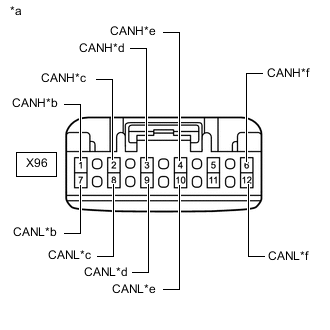
*a Front view of wire harness connector
(to No. 12 CAN Junction Connector)
*b to No. 2 CAN Junction Terminal *c to Tire Pressure Warning ECU and Receiver *d to Absorber Control ECU *e to No. 2 CAN Junction Connector *f to Skid Control ECU Assembly Disconnect the No. 12 CAN junction connector.
-
Measure the resistance according to the value(s) in the table below.
Standard Resistance Tester Connection Condition Specified Condition Connected to X96-1 (CANH) - X96-7 (CANL) Cable disconnected from negative (-) battery terminal 108 to 132 Ω No. 2 CAN junction terminal X96-2 (CANH) - X96-8 (CANL) Cable disconnected from negative (-) battery terminal 200 Ω or higher Tire pressure warning ECU and receiver X96-3 (CANH) - X96-9 (CANL) Cable disconnected from negative (-) battery terminal 200 Ω or higher Absorber control ECU X96-4 (CANH) - X96-10 (CANL) Cable disconnected from negative (-) battery terminal 108 to 132 Ω No. 2 CAN junction connector X96-6 (CANH) - X96-12 (CANL) Cable disconnected from negative (-) battery terminal 200 Ω or higher Skid control ECU assembly Result Result Proceed to OK A NG (No. 2 CAN junction terminal CAN main wire) B NG (No. 2 CAN junction connector CAN main wire) C NG (Wire to ECU or sensor) D
A
REPLACE NO. 12 CAN JUNCTION CONNECTOR
B
REPAIR OR REPLACE CAN MAIN WIRE OR CONNECTOR (NO. 12 CAN JUNCTION CONNECTOR - NO. 2 CAN JUNCTION TERMINAL)
D
GO TO STEP 20 Click here
C
-
-
CONNECT CONNECTOR
-
Reconnect the X96 No. 12 CAN junction connector.
Result Proceed to NEXT
NEXT
-
-
CHECK FOR SHORT IN CAN BUS WIRES (NO. 2 CAN JUNCTION CONNECTOR)
-
Disconnect the No. 2 CAN junction connector.
*a Front view of wire harness connector
(to No. 2 CAN Junction Connector)
*b to Pedestrian Detection ECU Assembly *c to Front Steering Control ECU (w/ Variable Gear Ratio Steering System) *d to Yaw Rate Sensor *e to Airbag ECU Assembly *f to Steering Sensor *g to No. 13 CAN Junction Connector *h to No. 12 CAN Junction Connector -
Measure the resistance according to the value(s) in the table below.
Standard Resistance *: w/ Variable Gear Ratio Steering SystemTester Connection Condition Specified Condition Connected to P108-1 (CANH) - P108-12 (CANL) Cable disconnected from negative (-) battery terminal 200 Ω or higher Pedestrian detection ECU assembly P108-2 (CANH) - P108-13 (CANL) Cable disconnected from negative (-) battery terminal 200 Ω or higher Front steering control ECU* P108-4 (CANH) - P108-15 (CANL) Cable disconnected from negative (-) battery terminal 200 Ω or higher Yaw rate sensor P108-5 (CANH) - P108-16 (CANL) Cable disconnected from negative (-) battery terminal 200 Ω or higher Airbag ECU assembly P108-6 (CANH) - P108-17 (CANL) Cable disconnected from negative (-) battery terminal 200 Ω or higher Steering sensor P108-7 (CANH) - P108-18 (CANL) Cable disconnected from negative (-) battery terminal 108 to 132 Ω No. 13 CAN junction connector P108-8 (CANH) - P108-19 (CANL) Cable disconnected from negative (-) battery terminal 108 to 132 Ω No. 12 CAN junction connector
Result Result Proceed to OK A NG (No. 12 CAN junction connector CAN main wire) B NG (No. 13 CAN junction connector CAN main wire) C NG (Wire to ECU or sensor) D
A
REPLACE NO. 2 CAN JUNCTION CONNECTOR
B
REPAIR OR REPLACE CAN MAIN WIRE OR CONNECTOR (NO. 2 CAN JUNCTION CONNECTOR - NO. 12 CAN JUNCTION CONNECTOR)
D
GO TO STEP 20 Click here
C
-
-
CONNECT CONNECTOR
-
Reconnect the P108 No. 2 CAN junction connector.
Result Proceed to NEXT
NEXT
-
-
CHECK FOR SHORT IN CAN BUS WIRES (NO. 13 CAN JUNCTION CONNECTOR)
Tech Tips
-
Before disconnecting the connectors, make a note of where it is connected.
-
Reconnect the connector to its original position.
-
Disconnect the No. 13 CAN junction connectors.
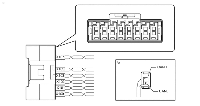
*1 No. 13 CAN Junction Connector - - *a Rear view of wire harness connector
(to No. 13 CAN Junction Connector)
- - Wiring Color Code Color (CANH Side) Color (CANL Side) Connect to X100 V P Parking brake ECU assembly X101 LG P Rear steering control ECU* X102 B P Rack and pinion power steering gear assembly X103 GR P No. 2 CAN junction connector X105 L P Central gateway ECU (network gateway ECU) X107 R P No. 3 CAN junction terminal *: w/ Dynamic Rear Steering System
-
Measure the resistance according to the value(s) in the table below.
Standard Resistance *: w/ Dynamic Rear Steering SystemTester Connection Condition Specified Condition Connected to X100-1 (CANH) - X100-2 (CANL) Cable disconnected from negative (-) battery terminal 200 Ω or higher Parking brake ECU assembly X101-1 (CANH) - X101-2 (CANL) Cable disconnected from negative (-) battery terminal 200 Ω or higher Rear steering control ECU* X102-1 (CANH) - X102-2 (CANL) Cable disconnected from negative (-) battery terminal 200 Ω or higher Rack and pinion power steering gear assembly X103-1 (CANH) - X103-2 (CANL) Cable disconnected from negative (-) battery terminal 108 to 132 Ω No. 2 CAN junction connector X105-1 (CANH) - X105-2 (CANL) Cable disconnected from negative (-) battery terminal 200 Ω or higher Central gateway ECU (network gateway ECU) X107-1 (CANH) - X107-2 (CANL) Cable disconnected from negative (-) battery terminal 108 to 132 Ω No. 3 CAN junction terminal
Result Result Proceed to OK A NG (No. 2 CAN junction connector CAN main wire) B NG (No. 3 CAN junction terminal CAN main wire) C NG (Central gateway ECU [network gateway ECU] CAN branch wire) D NG (Wire to ECU or sensor) E
A
REPLACE NO. 13 CAN JUNCTION CONNECTOR
B
REPAIR OR REPLACE CAN MAIN WIRE OR CONNECTOR (NO. 13 CAN JUNCTION CONNECTOR - NO. 2 CAN JUNCTION CONNECTOR)
C
REPAIR OR REPLACE CAN MAIN WIRE OR CONNECTOR (NO. 13 CAN JUNCTION CONNECTOR - NO. 3 CAN JUNCTION TERMINAL)
D
REPAIR OR REPLACE CAN BRANCH WIRE OR CONNECTOR (NO. 13 CAN JUNCTION CONNECTOR - CENTRAL GATEWAY ECU [NETWORK GATEWAY ECU])
E
-
-
CHECK FOR SHORT IN CAN BUS WIRES (ECU, SENSOR)
-
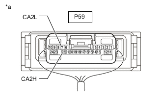
*a Component with harness connected
(Central Gateway ECU [Network Gateway ECU])
Reconnect all wire harness connectors.
-
Disconnect the connector that includes terminals CANH and CANL from the ECU or sensor to which the short circuited branch line is connected.
-
Measure the resistance according to the value(s) in the table below.
Standard Resistance Tester Connection Condition Specified Condition P59-22 (CA2H) - P59-7 (CA2L) Cable disconnected from negative (-) battery terminal 54 to 69 Ω Tech Tips
If the resistance becomes normal (between 54 and 69 Ω) when the connector is disconnected from the ECU or sensor, there may be a short in the ECU or sensor.
Result Result OK NG
OK
REPLACE ECU OR SENSOR
NG
REPAIR OR REPLACE HARNESS OR CONNECTOR
-