REAR NO. 1 SEAT ASSEMBLY(for 60/40 Split Seat Type RH Side) REMOVAL
CAUTION / NOTICE / HINT
The necessary procedures (adjustment, calibration, initialization or registration) that must be performed after parts are removed and installed, or replaced during rear No. 1 seat assembly removal/installation are shown below.
| Replaced Part or Performed Procedure | Necessary Procedures | Effect/Inoperative Function When Necessary Procedures are not Performed | Link |
|---|---|---|---|
| Disconnect cable from negative battery terminal | Memorize steering angle neutral point | LKA/LDA System | |
| Intelligent Clearance Sonar System*1 | |||
| Pre-crash Safety System | |||
| Lighting System (EXT)
|
|||
| Adaptive High Beam System | |||
| Drive the vehicle until stop and start control is permitted (approximately 15 to 60 minutes) | Stop and Start System | ||
| Memorize steering angle neutral point | Parking Assist Monitor System (w/ Parallel Parking Assist Function) | ||
| Parking Assist Monitor System (w/o Parallel Parking Assist Function) | |||
| Panoramic View Monitor System | |||
| Initialize back door lock | Power Door Lock Control System | ||
| Reset back door close position | Power Back Door System |
*1: When performing learning using the GTS.
CAUTION:
-
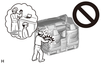
Some of these service operations affect the SRS airbag system. Read the precautionary notices concerning the SRS airbag system before servicing.
-
Wear protective gloves. Sharp areas on the seat frame may injure your hands.
PROCEDURE
-
PRECAUTION
Note
After turning the engine switch off, waiting time may be required before disconnecting the cable from the negative (-) battery terminal. Therefore, make sure to read the disconnecting the cable from the negative (-) battery terminal notices before proceeding with work.
-
DISCONNECT CABLE FROM NEGATIVE BATTERY TERMINAL
CAUTION:
-
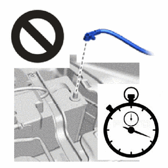
Wait at least 90 seconds after disconnecting the cable from the negative (-) battery terminal to disable the SRS system.
-
If an SRS part is accidentally deployed, it may cause a serious injury.
Note
When disconnecting the cable, some systems need to be initialized after the cable is reconnected.
-
-
REMOVE REAR SEAT HEADREST ASSEMBLY
-
Remove the rear seat headrest assembly.
-
-
REMOVE REAR SEAT CENTER HEADREST ASSEMBLY
-
Remove the rear seat center headrest assembly.
-
-
REMOVE REAR DOOR SCUFF PLATE RH
-
REMOVE SEAT INNER TRACK BRACKET COVER RH
-
Operate the seat track adjusting handle and move the rear No. 1 seat assembly RH to the foremost position.
-
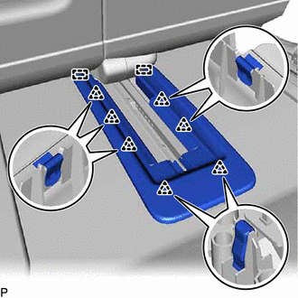
Disengage the 7 clips and 2 guides, and remove the seat inner track bracket cover RH.
-
-
REMOVE REAR SEAT OUTER TRACK BRACKET COVER RH
-
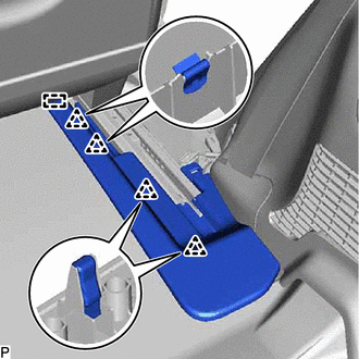
Disengage the 4 clips and guide, and remove the rear seat outer track bracket cover RH.
-
-
REMOVE REAR SEAT OUTER TRACK BRACKET COVER RH
-
Operate the seat track adjusting handle and move the rear No. 1 seat assembly RH to the rearmost position.
-
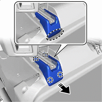

Place Hand Here 
Remove in this Direction Disengage the 2 claws and 2 guides to remove the rear seat outer track bracket cover RH as shown in the illustration.
-
-
REMOVE REAR SEAT INNER TRACK BRACKET COVER RH
Tech Tips
Use the same procedure as for the rear seat outer track bracket cover RH.
-
REMOVE REAR NO. 1 SEAT ASSEMBLY RH
-
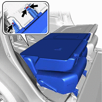
Disconnect the rear seat airbag assembly connector.
Note
When disconnecting any airbag connector, take care not to damage the airbag wire harness.
-
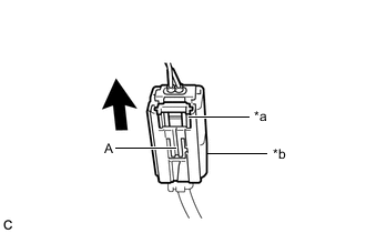
*a White Housing Lock *b Yellow CPA 
Slide Push down the white housing lock and slide the yellow CPA. (At this time, the connector cannot be disconnected yet.)
-
Push down the white housing lock again and disconnect the connector.
Note
Do not push the part (A) shown in the illustration when disconnecting the connector.
-
-
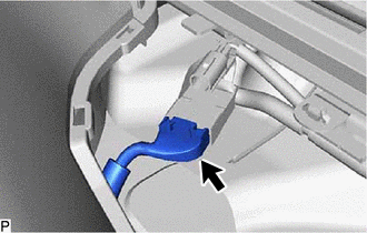
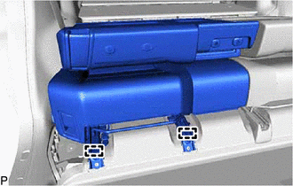
Disconnect the connector.
-
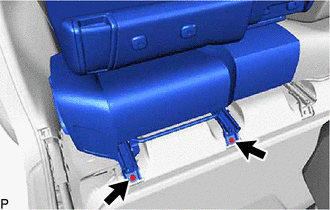
Remove the 2 bolts.
-
Operate the seat track adjusting handle and move the rear No. 1 seat assembly RH to the foremost position.
-
Remove the 3 bolts.
-
Disengage the 2 pins and remove the rear No. 1 seat assembly RH.
Note
Be careful not to damage the rear No. 1 seat assembly RH, vehicle body or vehicle interior.
-