STEERING PAD REMOVAL

CAUTION / NOTICE / HINT
The necessary procedures (adjustment, calibration, initialization, or registration) that must be performed after parts are removed, installed, or replaced during the horn button assembly removal/installation are shown below.
| Replacement Part or Procedure | Necessary Procedure | Effect/Inoperative Function When Necessary Procedures are not Performed | Link |
|---|---|---|---|
| Disconnect cable from negative battery terminal | Memorize steering angle neutral point | LKA/LDA System | |
| Intelligent clearance sonar system*1 | |||
| Pre-crash safety system | |||
| Lighting system (EXT)
|
|||
| Adaptive high beam system | |||
| Drive the vehicle until stop and start control is permitted (approximately 15 to 60 minutes) | Stop and start system | ||
| Memorize steering angle neutral point | Parking assist monitor system (w/ Parallel parking assist function) | ||
| Parking assist monitor system (w/o Parallel parking assist function) | |||
| Panoramic view monitor system | |||
| Initialize back door lock | Power door lock control system | ||
| Reset back door close position | Power back door system |
*1: When performing learning using the GTS.
PROCEDURE
-
PRECAUTION
Note
After turning the engine switch off, waiting time may be required before disconnecting the cable from the negative (-) battery terminal. Therefore, make sure to read the disconnecting the cable from the negative (-) battery terminal notices before proceeding with work.
-
DISCONNECT CABLE FROM NEGATIVE BATTERY TERMINAL
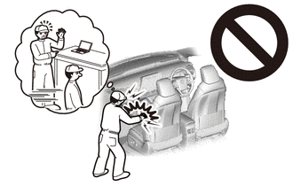
CAUTION:
Wait at least 90 seconds after disconnecting the cable from the negative (-) battery terminal to disable the SRS system.
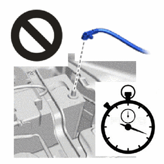
Note
When disconnecting the cable, some systems need to be initialized after the cable is reconnected.
-
REMOVE LOWER NO. 3 STEERING WHEEL COVER
-
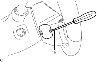
*a Protective Tape Using a screwdriver with its tip wrapped with protective tape, disengage the claw and guide to remove the lower No. 3 steering wheel cover.
-
-
REMOVE LOWER NO. 2 STEERING WHEEL COVER
-
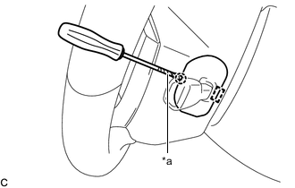
*a Protective Tape Using a screwdriver with its tip wrapped with protective tape, disengage the claw and guide to remove the lower No. 2 steering wheel cover.
-
-
REMOVE HORN BUTTON ASSEMBLY
CAUTION:
When storing the horn button assembly, keep the airbag deployment side facing upward.
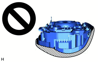

Deployment Side
-
Check that the engine switch is off.
-
Check that the cable is disconnected from the negative (-) battery terminal.
CAUTION:
Wait at least 90 seconds after disconnecting the cable from the negative (-) battery terminal to disable the SRS system.
-
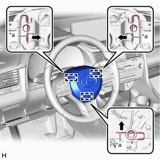
*a Torsion Spring Using a screwdriver, push in the 3 torsion springs to disengage the 3 pins as shown in the illustration.
Note
Do not drop the horn button assembly.
Tech Tips
Insert the screwdriver from the installation holes for the lower No. 3 steering wheel cover and lower No. 2 steering wheel cover.
-
Pull out the horn button assembly from the steering wheel assembly and hold the horn button assembly with one hand.
Note
When separating the horn button assembly, do not pull the airbag wire harness.
-
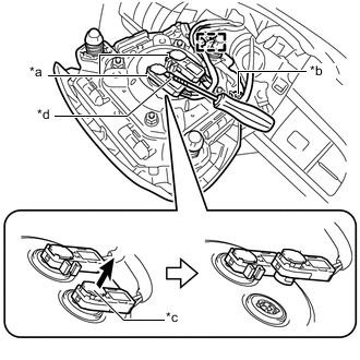
*a Airbag Connector *b Horn Connector *c Airbag Connector Lock *d Protective Tape Disconnect the horn connector from the horn button assembly.
-
Using a screwdriver with its tip wrapped with protective tape, release the 2 airbag connector locks.
-
Disconnect the 2 airbag connectors.
-
Disengage the wire harness clamp to remove the horn button assembly.
Note
When disconnecting any airbag connector, take care not to damage the airbag wire harness.
-