INTEGRATION RELAY REMOVAL
CAUTION / NOTICE / HINT
The necessary procedures (adjustment, calibration, initialization, or registration) that must be performed after parts are removed and installed, or replaced during integration relay removal/installation are shown below.
| Replaced Part or Performed Procedure | Necessary Procedure | Effect/Inoperative Function when Necessary Procedure not Performed | Link |
|---|---|---|---|
| Disconnect cable from negative battery terminal | Memorize steering angle neutral point | LKA/LDA System | |
| Intelligent clearance sonar system*1 | |||
| Pre-crash safety system | |||
| Lighting system (EXT)
|
|||
| Adaptive high beam system | |||
| Drive the vehicle until stop and start control is permitted (approximately 15 to 60 minutes) | Stop and start system | ||
| Memorize steering angle neutral point | Parking assist monitor system (w/ Parallel parking assist function) | ||
| Parking assist monitor system (w/o Parallel parking assist function) | |||
| Panoramic view monitor system | |||
| Initialize back door lock | Power door lock control system | ||
| Reset back door close position | Power back door system |
Click here Click here
PROCEDURE
-
PRECAUTION
Note
After turning the engine switch off, waiting time may be required before disconnecting the cable from the negative (-) battery terminal. Therefore, make sure to read the disconnecting the cable from the negative (-) battery terminal notices before proceeding with work.
-
DISCONNECT CABLE FROM NEGATIVE BATTERY TERMINAL
Note
When disconnecting the cable, some systems need to be initialized after the cable is reconnected.
-
DISCONNECT BRAKE MASTER CYLINDER RESERVOIR ASSEMBLY (for LHD)
-
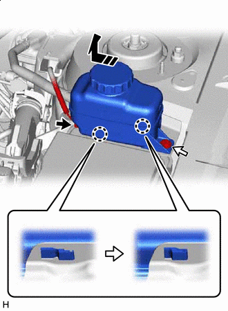

Connector 
Bolt 
Remove in this Direction Disconnect the reservoir level switch connector and remove the bolt from the brake master cylinder reservoir assembly.
-
Move the brake master cylinder reservoir assembly as shown in the illustration to disengage the 2 claws, and disconnect it.
-
-
REMOVE RESERVOIR BRACKET (for LHD)
-
REMOVE NO. 1 RELAY BLOCK COVER
-
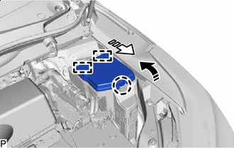
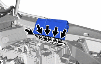
Remove in this Direction (1) 
Remove in this Direction (2) Disengage the claw and 2 guides to remove the No. 1 relay block cover as indicated by the arrows, in the order shown in the illustration.
-
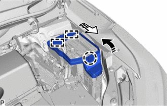
Remove in this Direction (1) Remove in this Direction (2) Disengage the claw and 2 guides to remove the No. 1 relay block cover as indicated by the arrows, in the order shown in the illustration.
-
-
REMOVE SEMICONDUCTOR POWER INTEGRATION ECU
-
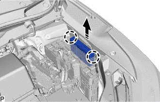
Remove in this Direction Disengage the 2 claws.
-
Pull up the semiconductor power integration ECU as shown in the illustration.
Note
When pulling the semiconductor power integration ECU, take care not to damage it.
-
Disconnect the 5 connectors and remove the semiconductor power integration ECU.
Note
When pulling the semiconductor power integration ECU, take care not to damage it.
-