GENERATOR REMOVAL

CAUTION / NOTICE / HINT
The necessary procedures (adjustment, calibration, initialization or registration) that must be performed after parts are removed and installed, or replaced during generator assembly removal/installation are shown below.
| Replaced Part or Performed Procedure | Necessary Procedure | Effect/Inoperative Function when Necessary Procedure not Performed | Link |
|---|---|---|---|
| Battery terminal is disconnected/reconnected | Memorize steering angle neutral point | LKA/LDA System | |
| Intelligent clearance sonar system*1 | |||
| Pre-crash safety system | |||
| Lighting system (EXT)
|
|||
| Adaptive high beam system | |||
| Drive the vehicle until stop and start control is permitted (approximately 15 to 60 minutes) | Stop and start system | ||
| Memorize steering angle neutral point | Parking Assist Monitor System (w/ Parallel Parking Assist Function) | ||
| Parking Assist Monitor System (w/o Parallel Parking Assist Function) | |||
| Panoramic view monitor system | |||
| Initialize back door lock | Power door lock control system | ||
| Reset back door close position | Power back door system |
*1: When performing learning using the GTS.
PROCEDURE
-
PRECAUTION
Note
After turning the engine switch off, waiting time may be required before disconnecting the cable from the negative (-) battery terminal. Therefore, make sure to read the disconnecting the cable from the negative (-) battery terminal notices before proceeding with work.
-
DISCONNECT CABLE FROM NEGATIVE BATTERY TERMINAL
Note
When disconnecting the cable, some systems need to be initialized after the cable is reconnected.
-
REMOVE V-RIBBED BELT
-
REMOVE GENERATOR ASSEMBLY
-
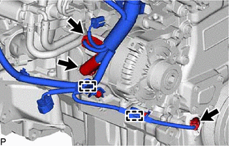
Disconnect the crankshaft position sensor connector, and disengage the 2 clamps.
-
Remove the terminal cap.
-
Remove the nut and disconnect the engine wire from terminal B.
-
Disconnect the generator assembly connector.
-
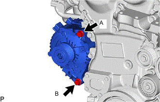
Fully loosen the bolt (A).
-
Remove the bolt (B) and generator assembly together with the bolt (A).
Tech Tips
There is not enough clearance to completely remove the bolt (A) from the generator assembly. Remove the generator assembly together with the bolt (A).
-
Remove the bolt from the generator assembly.
-
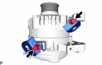
Remove the 2 bolts and 2 wire harness clamp brackets.
-