GENERATOR(for 150 A Type) REMOVAL

CAUTION / NOTICE / HINT
The necessary procedures (adjustment, calibration, initialization or registration) that must be performed after parts are removed and installed, or replaced during generator assembly removal/installation are shown below.
| Replaced Part or Performed Procedure | Necessary Procedure | Effect/Inoperative Function when Necessary Procedure not Performed | Link |
|---|---|---|---|
| Battery terminal is disconnected/reconnected | Memorize steering angle neutral point | LKA/LDA System | |
| Intelligent clearance sonar system*1 | |||
| Pre-crash safety system | |||
| Lighting system (EXT)
|
|||
| Adaptive high beam system | |||
| Drive the vehicle until stop and start control is permitted (approximately 15 to 60 minutes) | Stop and start system | ||
| Memorize steering angle neutral point | Parking Assist Monitor System (w/ Parallel Parking Assist Function) | ||
| Parking Assist Monitor System (w/o Parallel Parking Assist Function) | |||
| Panoramic view monitor system | |||
| Initialize back door lock | Power door lock control system | ||
| Reset back door close position | Power back door system |
*1: When performing learning using the GTS.
PROCEDURE
-
PRECAUTION
Note
After turning the engine switch off, waiting time may be required before disconnecting the cable from the negative (-) battery terminal. Therefore, make sure to read the disconnecting the cable from the negative (-) battery terminal notices before proceeding with work.
-
DISCONNECT CABLE FROM NEGATIVE BATTERY TERMINAL
Note
When disconnecting the cable, some systems need to be initialized after the cable is reconnected.
-
REMOVE RADIATOR ASSEMBLY
-
REMOVE V-RIBBED BELT
-
REMOVE GENERATOR ASSEMBLY
-
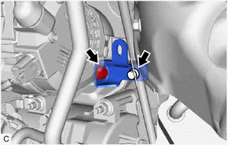
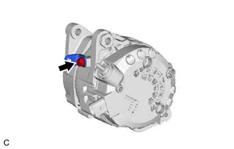
Open the terminal cap.
-
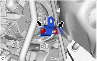
Remove the nut and disconnect the wire harness from terminal B.
-
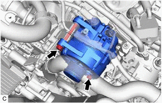
Disconnect the generator assembly connector.
-
Disconnect the compressor and magnetic clutch connector.
-
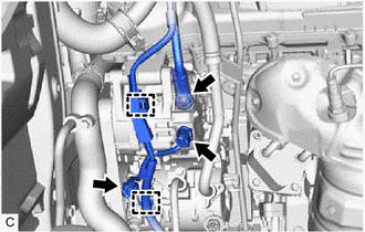
Disengage the 2 wire harness clamps.
-
Type A:
-
Remove the 2 bolts and generator assembly bracket.
-
-
Type B:
-
Remove the bolt, nut and generator assembly bracket.
-
-
Remove the 2 bolts and generator assembly.
-
Remove the bolt and wire harness clamp bracket.
-