CLEARANCE WARNING ECU(for RHD) REMOVAL

CAUTION / NOTICE / HINT
The necessary procedures (adjustment, calibration, initialization, or registration) that must be performed after parts are removed and installed, or replaced during clearance warning ECU assembly removal/installation are shown below.
| Replaced Part or Performed Procedure | Necessary Procedure | Effect/Inoperative Function when Necessary Procedure not Performed | Link |
|---|---|---|---|
| Disconnect cable from negative battery terminal | Memorize steering angle neutral point | LKA/LDA System | |
| Intelligent clearance sonar system*1 | |||
| Pre-crash safety system | |||
| Lighting system (EXT)
|
|||
| Adaptive high beam system | |||
| Drive the vehicle until stop and start control is permitted (approximately 15 to 60 minutes) | Stop and start system | ||
| Memorize steering angle neutral point | Parking assist monitor system (w/ Parallel parking assist function) | ||
| Parking assist monitor system (w/o Parallel parking assist function) | |||
| Panoramic view monitor system | |||
| Initialize back door lock | Power door lock control system | ||
| Reset back door close position | Power back door system | ||
| Replacement of clearance warning ECU assembly (w/o Intelligent clearance sonar system) | Registration of bumper type | LEXUS parking assist-sensor system (w/o Intelligent clearance sonar system) | |
| Replacement of clearance warning ECU assembly (w/ Intelligent clearance sonar system) |
|
|
*1: When performing learning using the GTS.
PROCEDURE
-
PRECAUTION
Note
After turning the engine switch off, waiting time may be required before disconnecting the cable from the negative (-) battery terminal. Therefore, make sure to read the disconnecting the cable from the negative (-) battery terminal notices before proceeding with work.
-
DISCONNECT CABLE FROM NEGATIVE BATTERY TERMINAL
Note
When disconnecting the cable, some systems need to be initialized after the cable is reconnected.
-
REMOVE LOWER NO. 1 INSTRUMENT PANEL FINISH PANEL
-
REMOVE INSTRUMENT PANEL GARNISH LH
-
REMOVE FRONT DOOR SCUFF PLATE LH
-
REMOVE COWL SIDE TRIM BOARD LH
-
REMOVE NO. 2 INSTRUMENT PANEL UNDER COVER SUB-ASSEMBLY
-
REMOVE GLOVE COMPARTMENT DOOR ASSEMBLY
-
REMOVE ECU INTEGRATION BOX LH
-
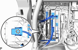
Disengage the claw.
-
Disconnect each connector.
-
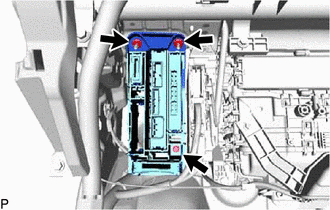
Remove the bolt and 2 nuts and ECU integration box LH.
-
-
REMOVE CLEARANCE WARNING ECU ASSEMBLY
-
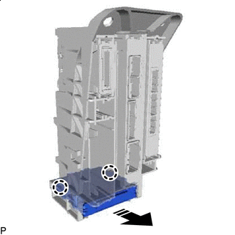

Remove in this Direction Disengage the 2 claws and remove the clearance warning ECU assembly as shown in the illustration.
-