INSTRUMENT PANEL SAFETY PAD REMOVAL
CAUTION / NOTICE / HINT
The necessary procedures (adjustment, calibration, initialization or registration) that must be performed after parts are removed and installed, or replaced during instrument panel safety pad removal/installation are shown below.
| Replaced Part or Performed Procedure | Necessary Procedure | Effect/Inoperative Function when Necessary Procedure not Performed | Link |
|---|---|---|---|
| Disconnect cable from negative battery terminal | Memorize steering angle neutral point | LKA/LDA System | |
| Pre-crash safety system | |||
| Lighting system (EXT)
|
|||
| Adaptive high beam system | |||
| Drive the vehicle until stop and start control is permitted (approximately 15 to 60 minutes) | Stop and start system | ||
| Memorize steering angle neutral point | Parking assist monitor system (w/ Parallel parking assist function) | ||
| Parking assist monitor system (w/o Parallel parking assist function) | |||
| Panoramic view monitor system | |||
| Initialize back door lock | Power door lock control system | ||
| Reset back door close position | Power back door system | ||
| Removal/installation of the spiral cable with sensor sub-assembly |
|
Parking assist monitor system (w/ Parallel Parking Assist Function) | Click here for Initialization Click here for Calibration |
| Parking assist monitor system (w/o Parallel Parking Assist Function) | Click here for Initialization Click here for Calibration |
||
| Steering angle neutral point (Initialize panoramic view monitor system) | Panoramic view monitor system | Click here for Initialization Click here for Calibration |
CAUTION:
Some of these service operations affect the SRS airbag system. Read the precautionary notices concerning the SRS airbag system before servicing.
PROCEDURE
-
PRECAUTION
Note
After turning the engine switch off, waiting time may be required before disconnecting the cable from the negative (-) battery terminal. Therefore, make sure to read the disconnecting the cable from the negative (-) battery terminal notices before proceeding with work.
-
REMOVE HEADLIGHT DIMMER SWITCH ASSEMBLY
-
REMOVE CONSOLE BOX ASSEMBLY
-
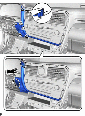
REMOVE INSTRUMENT PANEL GARNISH LH
-

Remove in this Direction Using a moulding remover B, disengage the 8 clips to remove the instrument panel garnish LH as shown in the illustration.
-
-
REMOVE FRONT DOOR SCUFF PLATE LH
-
REMOVE COWL SIDE TRIM BOARD LH
-
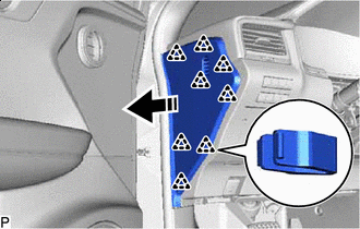
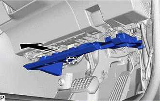
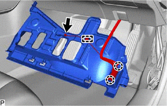
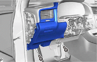
REMOVE NO. 1 INSTRUMENT PANEL UNDER COVER SUB-ASSEMBLY
-
for LHD:
-
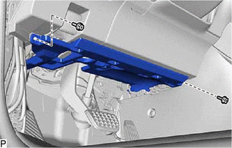
Remove the 2 screws <D>.
-
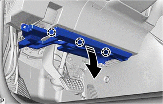
Remove in this Direction Disengage the 3 claws as shown in the illustration.
-
Remove in this Direction Disengage the 2 guides as shown in the illustration.
-
Disengage the 2 claws to disconnect the DLC3 connector.
-
Disconnect the connector.
-
Disengage the clamp to remove the No. 1 instrument panel under cover sub-assembly.
-
-
for RHD:
-
Remove the 2 screws <D>.
-
Remove in this Direction Disengage the 3 claws as shown in the illustration.
-
Remove in this Direction Disengage the guide as shown in the illustration.
-
Disengage the 2 claws to disconnect the DLC3 connector.
-
Disconnect the connector.
-
Disengage the clamp to remove the No. 1 instrument panel under cover sub-assembly.
-
-
-
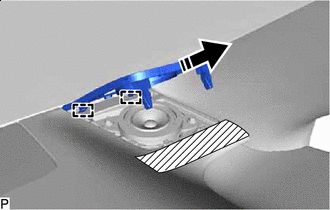
DISCONNECT HOOD LOCK CONTROL LEVER SUB-ASSEMBLY
-
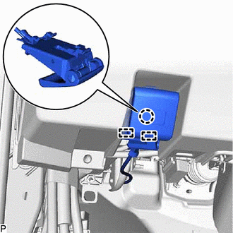
Disengage the claw and 2 guides to disconnect the hood lock control lever sub-assembly.
-
-
REMOVE LOWER INSTRUMENT PANEL FINISH PANEL SUB-ASSEMBLY
-
for LHD:
-
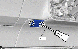
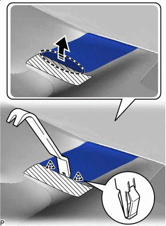
*a Protective Tape Using a screwdriver with its tip wrapped with protective tape, disengage the 2 claws to disconnect the instrument panel hole cover.
-
Remove the 2 screws <D>.
-
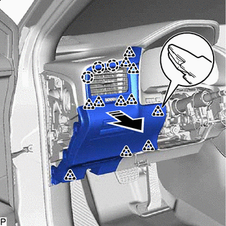
Remove in this Direction Disengage the 11 clips and 3 claws as shown in the illustration.
-
-
for RHD:
-
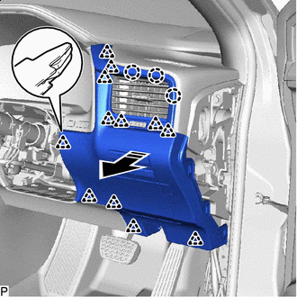
Remove in this Direction Disengage the 12 clips and 3 claws as shown in the illustration.
-
-
Disconnect each connector to remove the lower instrument panel finish panel sub-assembly.
-
-
REMOVE LOWER INSTRUMENT FINISH PANEL SUB
-
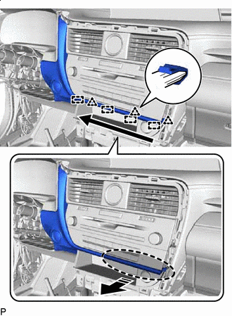

Place Hand Here Remove in this Direction 
Order of Removal Disengage the 3 clips and 4 guides as shown in the illustration.
-
Place Hand Here Remove in this Direction Disengage the 6 clips as shown in the illustration.
-
Disconnect the connector to remove the lower instrument finish panel sub.
-
-
REMOVE LOWER NO. 1 INSTRUMENT PANEL AIRBAG ASSEMBLY
-
REMOVE INSTRUMENT CLUSTER FINISH PANEL SUB-ASSEMBLY
-
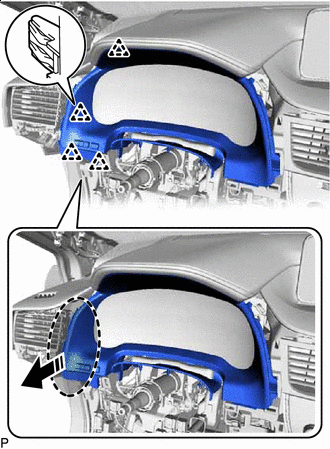
Place Hand Here Remove in this Direction Disengage the 4 clips as shown in the illustration.
-
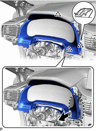
Place Hand Here Remove in this Direction Disengage the 3 clips as shown in the illustration.
-
Disconnect the connector to remove the instrument cluster finish panel sub-assembly.
-
-
REMOVE COMBINATION METER ASSEMBLY
-
REMOVE COOLER (ROOM TEMP. SENSOR) THERMISTOR
-
REMOVE RADIO RECEIVER ASSEMBLY WITH REGISTER
-
REMOVE CONSOLE BOX ASSEMBLY
-
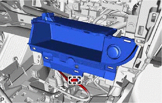
Disengage the clamp.
-
Place Hand Here Remove in this Direction Disengage the 5 clips as shown in the illustration.
-
Disconnect each connector to remove the console box assembly.
-
-
REMOVE CENTER INSTRUMENT CLUSTER FINISH PANEL SUB-ASSEMBLY (for 12.3 Inch Display)
-

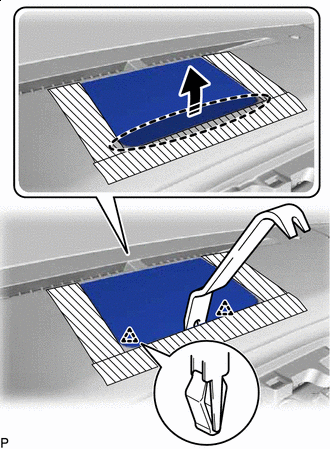
Protective Tape Apply protective tape to the areas shown in the illustration.
-
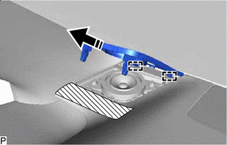
Insert Moulding Remover A Here Remove in this Direction Using a moulding remover A, disengage the 3 clips as shown in the illustration.
-
Remove in this Direction Disengage the 5 guides to remove the center instrument cluster finish panel sub-assembly as shown in the illustration.
-
-
REMOVE INSTRUMENT PANEL FINISH PANEL SUB-ASSEMBLY (for 12.3 Inch Display)
-
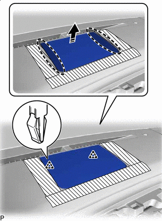
Protective Tape Apply protective tape to the areas shown in the illustration.
-
Insert Moulding Remover A Here Remove in this Direction Using a moulding remover A, disengage the 2 clips as shown in the illustration.
-
Insert Moulding Remover A Here Remove in this Direction Using a moulding remover A, disengage the 5 claws, 4 clips and 7 guides to remove the instrument panel finish panel sub-assembly as shown in the illustration.
-
-
REMOVE CENTER INSTRUMENT CLUSTER FINISH PANEL SUB-ASSEMBLY (for 8 Inch Display)
-
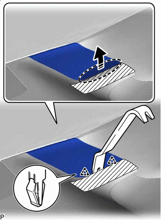
Protective Tape Apply protective tape to the areas shown in the illustration.
-
Insert Moulding Remover A Here Remove in this Direction Using a moulding remover A, disengage the 3 clips, 2 claws and guide as shown in the illustration.
-
Remove in this Direction Disengage the 5 guides to remove the center instrument cluster finish panel sub-assembly as shown in the illustration.
-
-
REMOVE INSTRUMENT PANEL FINISH PANEL SUB-ASSEMBLY (for 8 Inch Display)
-
Protective Tape Apply protective tape to the areas shown in the illustration.
-
Insert Moulding Remover B Here Remove in this Direction Using a moulding remover B, disengage the 2 clips as shown in the illustration.
-
Insert Moulding Remover A Here Remove in this Direction Using a moulding remover A, disengage the claw, 5 clips and 4 guides to remove the instrument panel finish panel sub-assembly as shown in the illustration.
-
-
REMOVE ACCESSORY METER ASSEMBLY (for 12.3 Inch Display)
-
REMOVE MULTI-DISPLAY ASSEMBLY (for 8 Inch Display)
-
REMOVE INSTRUMENT PANEL GARNISH RH
-
Remove in this Direction Using a moulding remover B, disengage the 8 clips as shown in the illustration.
-
w/ Airbag Cut Off Switch:
-
Disconnect the connector.
-
-
Remove the instrument panel garnish RH.
-
-
REMOVE FRONT DOOR SCUFF PLATE RH
Tech Tips
Use the same procedure as for the LH side.
-
REMOVE COWL SIDE TRIM BOARD RH
Tech Tips
Use the same procedure as for the LH side.
-
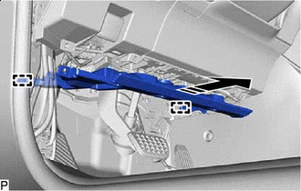
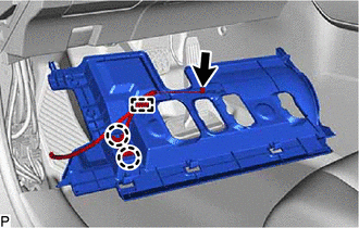
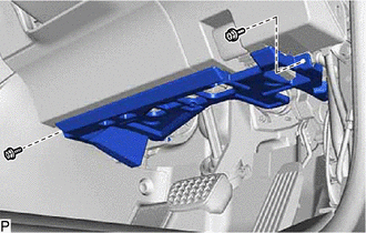
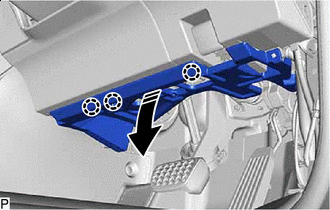
REMOVE NO. 2 INSTRUMENT PANEL UNDER COVER SUB-ASSEMBLY
-
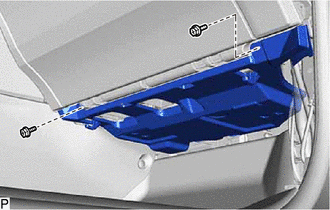
Remove the 2 screws <D>.
-
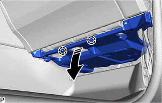
Remove in this Direction Disengage the 2 claws as shown in the illustration.
-
Remove in this Direction Disengage the 2 guides as shown in the illustration.
-
Disconnect the connector to remove the No. 2 instrument panel under cover sub-assembly.
-
-
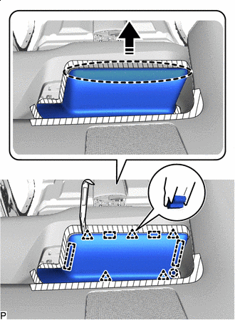
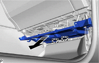
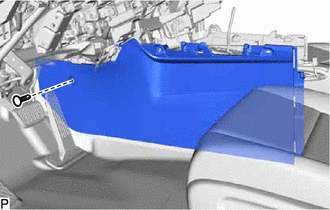
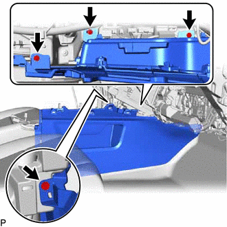
REMOVE GLOVE COMPARTMENT DOOR ASSEMBLY
-
Open the glove compartment door assembly.
-
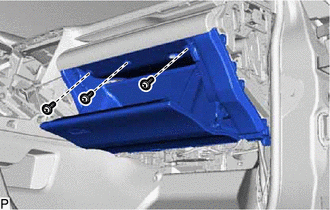
Remove the 3 screws <E>.
-
Close the glove compartment door assembly.
-
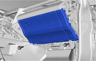
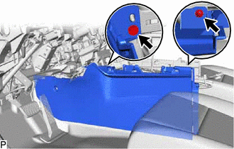
Remove the 2 bolts <B> or <C>.
-
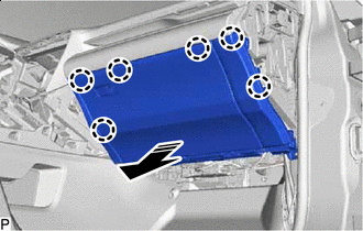
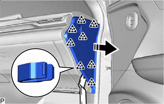
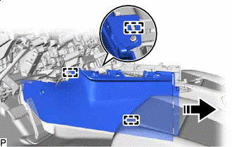
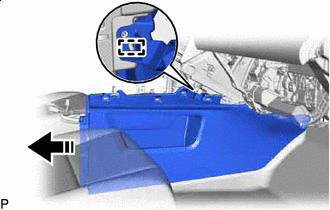
Remove in this Direction Disengage the 6 claws as shown in the illustration.
-
Disconnect the connector.
-
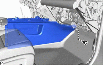
Disengage the clamp to remove the glove compartment door assembly.
-
-
REMOVE NO. 1 INSTRUMENT PANEL SPEAKER PANEL SUB-ASSEMBLY
-
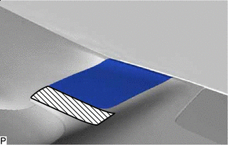
Protective Tape Apply protective tape to the area shown in the illustration.
-
Insert Moulding Remover B Here Remove in this Direction Using a moulding remover B, disengage the 2 clips as shown in the illustration.
-
Remove in this Direction Disengage the 2 guides to remove the No. 1 instrument panel speaker panel sub-assembly as shown in the illustration.
-
-
REMOVE FRONT NO. 2 SPEAKER ASSEMBLY (for LH Side)
-
REMOVE FRONT PILLAR GARNISH LH
-
REMOVE NO. 1 SPEAKER OPENING COVER ASSEMBLY
-
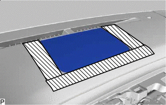
Protective Tape Apply protective tape to the areas shown in the illustration.
-
Insert Moulding Remover B Here Remove in this Direction Using a moulding remover B, disengage the 2 clips as shown in the illustration.
-
Place Hand Here Remove in this Direction Disengage the 2 clips to remove the No. 1 speaker opening cover assembly as shown in the illustration.
-
-
REMOVE FRONT NO. 3 SPEAKER ASSEMBLY
-
REMOVE NO. 2 INSTRUMENT PANEL SPEAKER PANEL SUB-ASSEMBLY
-
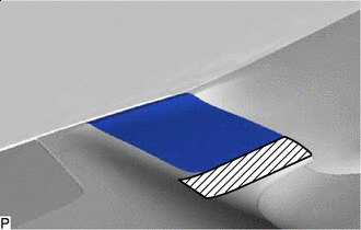
Protective Tape Apply protective tape to the area shown in the illustration.
-
Insert Moulding Remover B Here Remove in this Direction Using a moulding remover B, disengage the 2 clips as shown in the illustration.
-
Remove in this Direction Disengage the 2 guides to remove the No. 2 instrument panel speaker panel sub-assembly as shown in the illustration.
-
-
REMOVE FRONT NO. 2 SPEAKER ASSEMBLY (for RH Side)
Tech Tips
Use the same procedure as for the LH side.
-
REMOVE FRONT PILLAR GARNISH RH
Tech Tips
Use the same procedure as for the LH side.
-
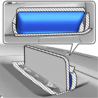
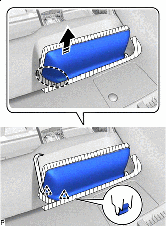
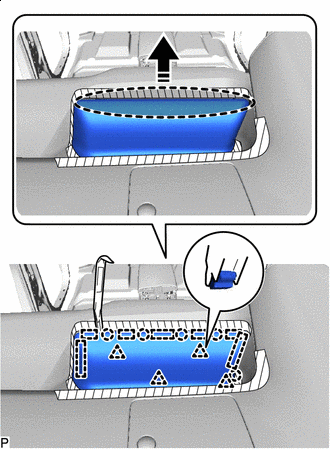
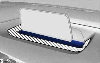
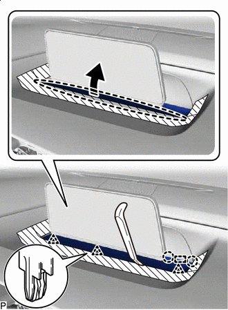
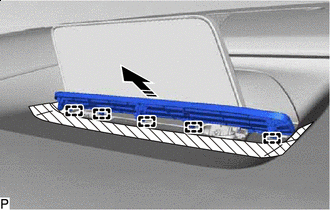
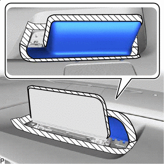
REMOVE NO. 1 INSTRUMENT PANEL REGISTER ASSEMBLY
-
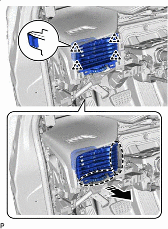
Place Hand Here Remove in this Direction Disengage the 4 clips to remove the No. 1 instrument panel register assembly as shown in the illustration.
-
-
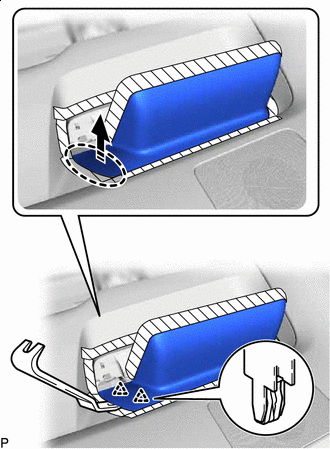
REMOVE NO. 2 INSTRUMENT CLUSTER MOULDING
-
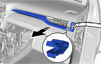
Remove in this Direction Using a moulding remover A, disengage the 2 clips as shown in the illustration.
-
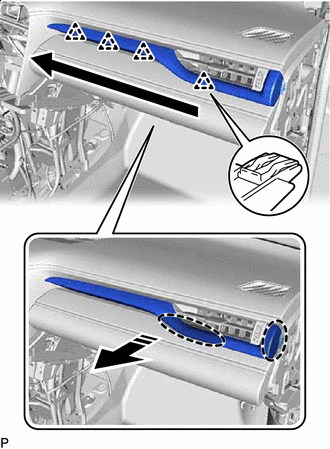
Place Hand Here Remove in this Direction Order of Removal Disengage the 4 clips to remove the No. 2 instrument cluster moulding as shown in the illustration.
-
w/ Interior Illumination:
-
Disconnect the connector.
-
-
-
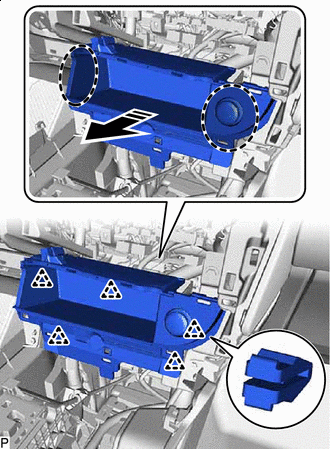
REMOVE FRONT NO. 1 CONSOLE BOX INSERT
-
Using a clip remover, remove the clip.
-
Remove the 2 screws <E>.
-
Remove in this Direction Disengage the 3 guides to remove the front No. 1 console box insert as shown in the illustration.
-
-
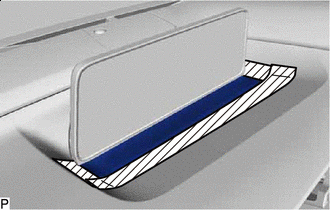
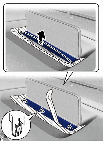
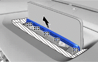
REMOVE FRONT NO. 2 CONSOLE BOX INSERT
-
Using a clip remover, remove the clip.
-
Remove the 4 screws <E>.
-
Remove in this Direction Disengage the guide to remove the front No. 2 console box insert as shown in the illustration.
-
-
DISCONNECT NO. 2 INSTRUMENT PANEL WIRE
-
REMOVE INSTRUMENT PANEL SAFETY PAD SUB-ASSEMBLY
-
Disconnect each connector.
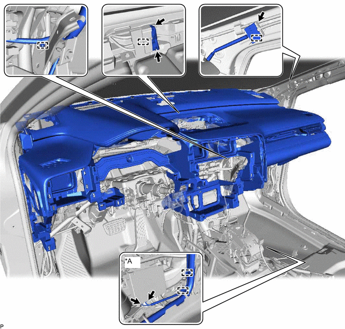
*A w/ Telematics Transceiver - - -
Disengage each clamp.
-
Remove the 2 clips.
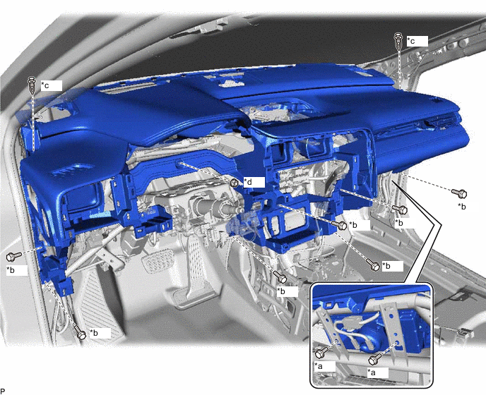
*a Bolt <A> *b Bolt <C> *c Clip *d Nut <G> -
Remove the 7 bolts <C>, 2 bolts <A> and nut <G>.
-
Disengage the 4 guides and remove the instrument panel safety pad sub-assembly as shown in the illustration.
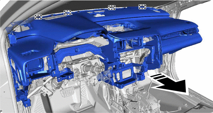
Remove in this Direction - - Note
-
Do not damage the instrument panel safety pad sub-assembly.
-
Do not allow the wire harnesses to interfere with the surrounding parts.
-
-