STEERING COLUMN ASSEMBLY REMOVAL
CAUTION / NOTICE / HINT
The necessary procedures (adjustment, calibration, initialization, or registration) that must be performed after parts are removed, installed, or replaced during the electric power steering column sub-assembly removal/installation are shown below.
| Replacement Part or Procedure | Necessary Procedures | Effects / Inoperative when not performed | Link |
|---|---|---|---|
| Replacement of the power steering ECU assembly |
|
|
|
| Replacement of the electric power steering column sub-assembly | Perform Torque Sensor Zero Point Calibration | ||
| Replacement of the steering lock actuator or upper bracket assembly | Perform code registration (Immobiliser system) |
|
See Service Bulletin for the registration method. |
| Removal/installation of the spiral cable with sensor sub-assembly |
|
Parking assist monitor system (w/ Parallel Parking Assist Function) | Click here for Initialization Click here for Calibration |
| Parking assist monitor system (w/o Parallel Parking Assist Function) | Click here for Initialization Click here for Calibration |
||
| Steering angle neutral point (Initialize panoramic view monitor system) | Panoramic view monitor system | Click here for Initialization Click here for Calibration |
|
| Disconnect cable from negative battery terminal | Memorize steering angle neutral point | LKA /LDA system | |
| Pre-crash safety system | |||
| Lighting system (EXT)
|
|||
| Adaptive high beam system | |||
| Drive the vehicle until stop and start control is permitted (approximately 15 to 60 minutes) | Stop and start system | ||
| Memorize steering angle neutral point | Parking Assist Monitor System (w/ Parallel Parking Assist Function) | ||
| Parking Assist Monitor System (w/o Parallel Parking Assist Function) | |||
| Panoramic view monitor system | |||
| Initialize back door lock | Power door lock control system | ||
| Reset back door close position | Power back door system |
PROCEDURE
-
PRECAUTION
-
CHANGE POWER TILT AND POWER TELESCOPIC STEERING COLUMN SYSTEM SETTINGS
-
Disable the auto tilt away function by changing the customize settings.
Note
Record the current customize setting (whether the auto tilt away function is enabled or disabled) in order to restore the current setting after finishing the operation.
Tech Tips
Performing the above operation causes the auto tilt away function to be disabled when the engine switch is turned off.
-
Turn the engine switch on (IG). Operate the tilt and telescopic switch to fully extend and lower the steering column assembly.
-
-
ALIGN FRONT WHEELS FACING STRAIGHT AHEAD
-
REMOVE HORN BUTTON ASSEMBLY
-
REMOVE STEERING WHEEL ASSEMBLY
-
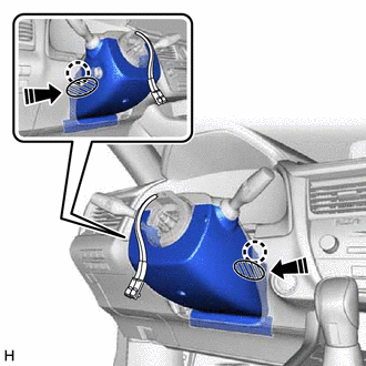
REMOVE LOWER STEERING COLUMN COVER
-
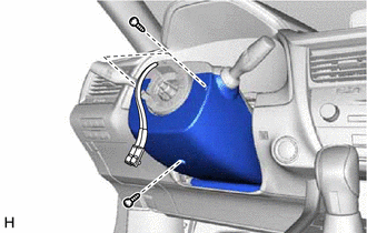
Remove the 3 screws.
-

Push Area 
Push in this direction While pressing the push area shown in the illustration to disengage the 2 claws, slightly lower the lower steering column cover.
-
-
REMOVE UPPER STEERING COLUMN COVER
-
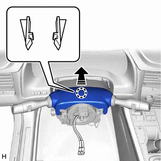
Separate in this direction Disengage the 2 claws and separate the upper steering column cover.
-
Disengage the 6 clips to remove the upper steering column cover.
-
-
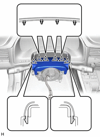
REMOVE TURN SIGNAL SWITCH ASSEMBLY WITH SPIRAL CABLE SUB-ASSEMBLY
Note
-
Do not replace the spiral cable with sensor sub-assembly with the battery connected and the engine switch on (IG).
-
Do not rotate the spiral cable with sensor sub-assembly without the steering wheel assembly installed, with the battery connected and the engine switch on (IG).
-
Ensure that the steering wheel assembly is installed and aligned straight when inspecting the steering sensor.
-
Disconnect each connector from the turn signal switch assembly with spiral cable sub-assembly.
-
Remove in this direction Disengage the 3 claws to remove the turn signal switch assembly with spiral cable sub-assembly from the steering column assembly.
-
-
REMOVE LOWER NO. 1 INSTRUMENT PANEL AIRBAG ASSEMBLY
-
REMOVE REMOTE TOUCH ASSEMBLY
-
REMOVE SHIFT LEVER KNOB SUB-ASSEMBLY
-
REMOVE CONSOLE PANEL SUB-ASSEMBLY
-
REMOVE MAYDAY BATTERY WITH BRACKET (w/ Telematics Transceiver)
-
REMOVE CONSOLE REAR END PANEL SUB-ASSEMBLY
-
REMOVE CONSOLE BOX ASSEMBLY
-
REMOVE FRONT NO. 1 CONSOLE BOX INSERT
-
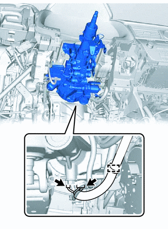
REMOVE NO. 4 AIR DUCT SUB-ASSEMBLY
-
Remove the bolt.
-
Disengage the 3 claws to remove the No. 4 air duct sub-assembly.
-
-
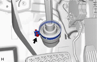
REMOVE STOP LIGHT SWITCH ASSEMBLY (for LHD)
-
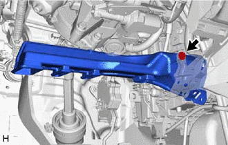
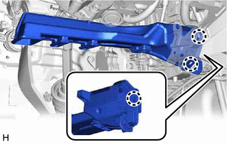
SEPARATE STEERING INTERMEDIATE SHAFT ASSEMBLY
-
REMOVE STEERING INTERMEDIATE SHAFT ASSEMBLY
-
Loosen the bolt.
-
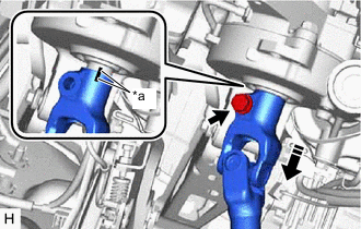
*a Matchmark Remove the bolt and slide the steering intermediate shaft assembly.
Note
Do not remove the steering intermediate shaft assembly from the steering column assembly.
-
Put matchmarks on the steering intermediate shaft assembly and the steering column assembly.
-
Remove the steering intermediate shaft assembly from the steering column assembly.
-
-
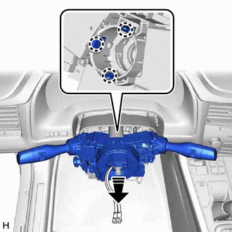
REMOVE STEERING COLUMN ASSEMBLY
-
Disconnect the 2 connectors.
-
Disengage the clamp.
-
Disconnect each connector and disengage each wire harness clamp from the steering column assembly.
-
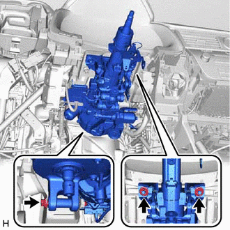
Remove the bolt, 2 nuts and steering column assembly.
-