VACUUM PUMP(for 2GR-FKS) REMOVAL
CAUTION / NOTICE / HINT
The necessary procedures (adjustment, calibration, initialization, or registration) that must be performed after parts are removed, installed, or replaced during vacuum pump assembly removal/installation are shown below.
| Replaced Part or Performed Procedure | Necessary Procedure | Effect/Inoperative Function when Necessary Procedure not Performed | Link |
|---|---|---|---|
| Battery terminal is disconnected/reconnected | Memorize steering angle neutral point | LKA/LDA System | |
| Intelligent clearance sonar system | |||
| Pre-Crash Safety System | |||
| Lighting System (EXT)
|
|||
| Adaptive High Beam System | |||
| Parking Assist Monitor System (w/ Parallel Parking Assist Function) | |||
| Parking Assist Monitor System (w/o Parallel Parking Assist Function) | |||
| Panoramic View Monitor System | |||
| Drive the vehicle until stop and start control is permitted (approximately 15 to 60 minutes) | Stop and start system | ||
| Initialize back door lock | Power door lock control system | ||
| Reset back door close position | Power back door system |
PROCEDURE
-
PRECAUTION
Note
After turning the engine switch off, waiting time may be required before disconnecting the cable from the negative (-) battery terminal. Therefore, make sure to read the disconnecting the cable from the negative (-) battery terminal notices before proceeding with work.
-
DISCONNECT CABLE FROM NEGATIVE BATTERY TERMINAL
Note
When disconnecting the cable, some systems need to be initialized after the cable is reconnected.
-
REMOVE THROTTLE BODY WITH MOTOR ASSEMBLY
-
REMOVE FRONT WHEEL LH
-
REMOVE COOL AIR INTAKE DUCT SEAL
-
REMOVE V-BANK COVER SUB-ASSEMBLY
-
REMOVE INLET AIR CLEANER ASSEMBLY
-
REMOVE AIR CLEANER FILTER ELEMENT SUB-ASSEMBLY
-
REMOVE AIR CLEANER CASE SUB-ASSEMBLY
-
REMOVE AIR CLEANER BRACKET
-
SEPARATE TRANSMISSION CONTROL CABLE ASSEMBLY
-
Remove the nut and separate the transmission control cable assembly from the transmission control shaft lever.
-
Using a screwdriver, disengage the 4 claws and disconnect the transmission control cable assembly with clip from the No. 1 transmission control cable bracket.
-
Using a screwdriver, disengage the 2 claws and remove the clip from the transmission control cable assembly.
-
-
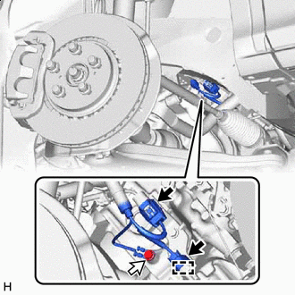
DISCONNECT AIR TUBE
-
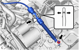
Slide the clip and disconnect the air tube from the vacuum pump assembly.
-
-
DISCONNECT VENTILATION HOSE
-
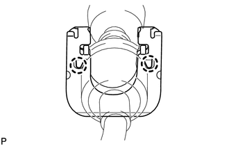
Slide the clip and disconnect the ventilation hose.
-
-
DISCONNECT HEATER WATER HOSE
-
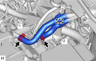
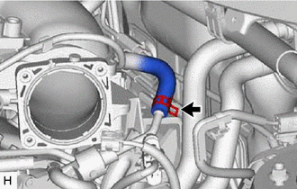
*1 Inlet Heater Water Hose *2 Outlet Heater Water Hose Disengage the clamp.
-
Slide the 2 clips and disconnect the inlet heater water hose and outlet heater water hose.
-
-
DISCONNECT VACUUM HOSE SUB-ASSEMBLY
-
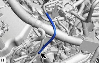
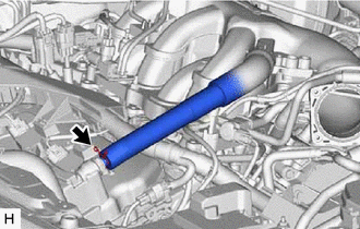
Disconnect the vacuum hose sub-assembly.
-
-
REMOVE NO. 2 ENGINE UNDER COVER
-
SEPARATE ENGINE WIRE
-

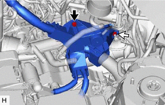
Connector 
Bolt Disconnect the 2 connectors.
-
Disengage the clamp.
-
Remove the bolt.
-
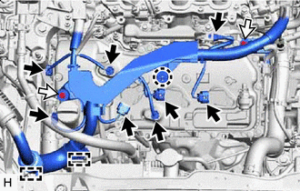
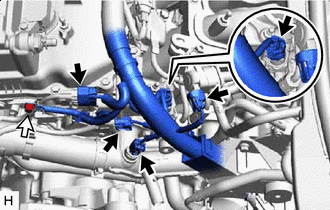
Connector Bolt Disconnect the 8 connectors.
-
Disengage the 2 clamps and claw.
-
Remove the 2 bolts.
-
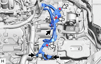
Connector Bolt Disconnect the 5 connectors.
-
Remove the bolt.
-
Disengage the 2 clamps.
-
Remove the 2 nuts.
-
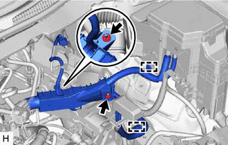
Connector Bolt 
Nut Disconnect the 3 connectors.
-
Remove the 3 bolts and nut.
-
Bolt Nut Remove the bolt and nut to separate the engine wire.
-
-
REMOVE VACUUM PUMP ASSEMBLY
-
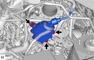
Remove the 3 bolts and vacuum pump assembly from the engine assembly.
-
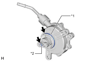
*1 No. 2 O-ring *2 No. 3 O-ring Remove the No. 2 O-ring and No. 3 O-ring from the vacuum pump assembly.
-