OIL PUMP REMOVAL
CAUTION / NOTICE / HINT
The necessary procedures (adjustment, calibration, initialization, or registration) that must be performed after parts are removed, installed, or replaced during the oil pump removal/installation are shown below.
| Replaced Part or Performed Procedure | Necessary Procedure | Effect/Inoperative Function when Necessary Procedure not Performed | Link | |
|---|---|---|---|---|
| Battery terminal is disconnected/reconnected | Memorize steering angle neutral point | LKA/LDA System | ||
| Pre-crash safety system | ||||
| Lighting system (EXT)
|
||||
| Adaptive high beam system | ||||
| Drive the vehicle until stop and start control is permitted (approximately 15 to 60 minutes) | Stop and start system | |||
| Memorize steering angle neutral point | Parking Assist Monitor System (w/ Parallel Parking Assist Function) | |||
| Parking Assist Monitor System (w/o Parallel Parking Assist Function) | ||||
| Panoramic view monitor system | ||||
| Initialize back door lock | Power door lock control system | |||
| Reset back door close position | Power back door system | |||
| Replacement of ECM | Perform Vehicle Identification Number (VIN) or frame number registration |
|
||
| ECU Communication ID Registration (Immobiliser system) | Engine start function | See Service Bulletin for the registration method. | ||
|
Inspection After Repair |
|
||
| Replacement of starter assembly*1 Note When the starter assembly is replaced, "ST relay" and "ST NO. 2 relay" must be also replaced. |
Clear Number of Starter Operations | Stop and start system | ||
| Replacement of battery*1 |
|
|||
|
Bleed the oil pump assembly with motor (continuously variable transaxle assembly) | |||
| Replacement of automatic transaxle assembly | Perform the following procedures in the order shown:
|
|
Click here for Initialization (U661E) Click here for Registration (U661E) Click here for Initialization (U661F) Click here for Registration (U661F) |
|
| Replacement of ECM (If possible, read the transaxle compensation code from the previous ECM) |
Possible to read transaxle compensation code | Perform the following procedures in the order shown:
|
||
| Impossible to read transaxle compensation code | Perform the following procedures in the order shown:
|
|||
| Suspension, tires, etc.*2 | Rear television camera assembly optical axis (Back camera position setting) | Parking assist monitor system (w/ Parallel Parking Assist Function) | Click here for Initialization Click here for Calibration |
|
| Parking assist monitor system (w/o parallel parking assist function) | Click here for Initialization Click here for Calibration |
|||
|
Panoramic view monitor system | Click here for Initialization Click here for Calibration |
||
| Initialize headlight ECU sub-assembly LH |
|
|||
| Front wheel alignment adjustment |
|
|
||
*2: The vehicle height changes because of suspension or tire replacement
*3: w/ TFT Meter Type
Note
Do not remove the oil pump and oil pump relief valve from the timing chain cover assembly.
PROCEDURE
-
INSTALL ENGINE TO ENGINE STAND
-
REMOVE IGNITION COIL ASSEMBLY
-
DISCONNECT ENGINE WIRE
-
REMOVE NO. 2 WATER BY-PASS PIPE
-
REMOVE NO. 1 FUEL PIPE SUB-ASSEMBLY (for High Pressure)
-
REMOVE FUEL PUMP ASSEMBLY (for High Pressure)
-
REMOVE NO. 2 VENTILATION HOSE
-
REMOVE FUEL PUMP PROTECTOR
-
DISCONNECT VACUUM TRANSMITTING HOSE ASSEMBLY
-
DISCONNECT NO. 2 VACUUM TRANSMITTING HOSE ASSEMBLY
-
REMOVE CYLINDER HEAD COVER SUB-ASSEMBLY
-
REMOVE V-RIBBED BELT
-
REMOVE CAMSHAFT TIMING OIL CONTROL SOLENOID ASSEMBLY
-
REMOVE V-RIBBED BELT TENSIONER ASSEMBLY
-
REMOVE IDLER PULLEY SUB-ASSEMBLY
-
REMOVE ENGINE MOUNTING BRACKET RH
-
REMOVE CRANKSHAFT PULLEY ASSEMBLY
-
REMOVE CRANKSHAFT POSITION SENSOR
-
REMOVE TIMING CHAIN COVER ASSEMBLY
-
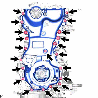
*a Nut Remove the 2 nuts and 19 bolts.
-
Remove the timing chain cover assembly by prying between the timing chain cover assembly and cylinder head sub-assembly, camshaft housing sub-assembly, cylinder block sub-assembly and stiffening crankcase assembly with a screwdriver as shown in the illustration.
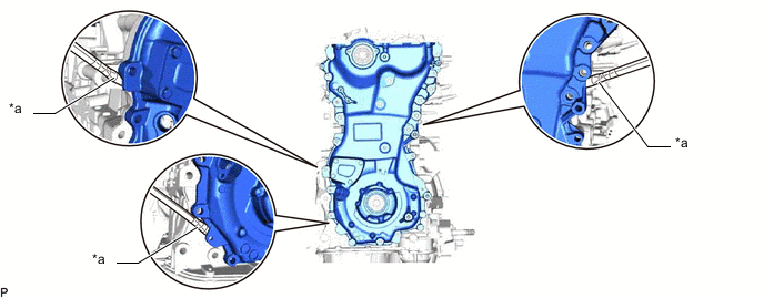
*a Protective Tape - - Note
Be careful not to damage the contact surfaces of the cylinder head sub-assembly, camshaft housing sub-assembly, cylinder block sub-assembly, stiffening crankcase assembly or timing chain cover assembly.
Tech Tips
Tape the screwdriver tip before use.
-
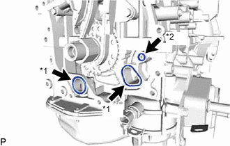
*1 Oil Pump Gasket *2 Oil Hole Cover Gasket Remove the 2 oil pump gaskets and oil hole cover gasket from the stiffening crankcase assembly.
-
-
REMOVE TIMING GEAR CASE OR TIMING CHAIN CASE OIL SEAL