CYLINDER BLOCK DISASSEMBLY
CAUTION / NOTICE / HINT
The necessary procedures (adjustment, calibration, initialization, or registration) that must be performed after parts are removed and installed, or replaced during engine unit removal/installation are shown below.
| Replaced Part or Performed Procedure | Necessary Procedure | Effect/Inoperative Function when Necessary Procedure not Performed | Link | |
|---|---|---|---|---|
| Battery terminal is disconnected/reconnected | Memorize steering angle neutral point | LKA/LDA System | ||
| Intelligent clearance sonar system*4 | ||||
| Pre-crash safety system | ||||
| Lighting system (EXT)
|
||||
| Adaptive high beam system | ||||
| Drive the vehicle until stop and start control is permitted (approximately 15 to 60 minutes) | Stop and start system | |||
| Memorize steering angle neutral point | Parking Assist Monitor System (w/ Parallel Parking Assist Function) | |||
| Parking Assist Monitor System (w/o Parallel Parking Assist Function) | ||||
| Panoramic view monitor system | ||||
| Initialize back door lock | Power door lock control system | |||
| Reset back door close position | Power back door system | |||
| Replacement of ECM | Perform Vehicle Identification Number (VIN) or frame number registration |
|
||
| ECU Communication ID Registration (Immobiliser system) | Engine start function | See Service Bulletin for the registration method. | ||
| Replacement of ECM (If possible, read the transaxle compensation code from the previous ECM) |
Possible to read transaxle compensation code | Perform the following procedures in the order shown:
|
|
Click here for Initialization (U661E) Click here for Registration (U661E) Click here for Initialization (U661F) Click here for Registration (U661F) |
| Impossible to read transaxle compensation code | Perform the following procedures in the order shown:
|
|||
| Piston ring | Clear Heavy Knock History | - | ||
|
Inspection After Repair |
|
||
| Replacement of starter assembly*1 Note When the starter assembly is replaced, "ST relay" and "ST NO. 2 relay" must be also replaced. |
Clear Number of Starter Operations | Stop and start system | ||
| Replacement of battery*1 |
|
|||
|
Bleed the oil pump assembly with motor (continuously variable transaxle assembly) | |||
| Replacement of automatic transaxle assembly | Perform the following procedures in the order shown:
|
|
Click here for Initialization (U661E) Click here for Registration (U661E) Click here for Initialization (U661F) Click here for Registration (U661F) |
|
| Suspension, tires, etc.*2 |
|
|
||
| Rear television camera assembly optical axis (Back camera position setting) | Parking assist monitor system (w/ Parallel Parking Assist Function) | Click here for Initialization Click here for Calibration |
||
| Parking assist monitor system (w/o parallel parking assist function) | Click here for Initialization Click here for Calibration |
|||
|
Panoramic view monitor system | Click here for Initialization Click here for Calibration |
||
| Initialize headlight ECU sub-assembly LH |
|
|||
| Front wheel alignment adjustment |
|
|
||
*2: The vehicle height changes because of suspension or tire replacement
*3: w/ TFT Meter Type
*4: When performing learning using the GTS.
Click here Click here
PROCEDURE
-
INSPECT CONNECTING ROD THRUST CLEARANCE
-
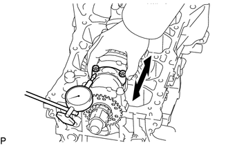
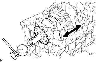
Using a dial indicator, measure the thrust clearance while moving the connecting rod sub-assembly back and forth.
Standard Thrust Clearance 0.160 to 0.512 mm (0.00630 to 0.0202 in.) Maximum Thrust Clearance 0.512 mm (0.0202 in.) If the thrust clearance is more than the maximum, replace the connecting rod sub-assembly. If necessary, replace the crankshaft.
-
-
INSPECT CONNECTING ROD OIL CLEARANCE
-
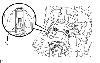
*a Alignment Mark Check the alignment marks on the connecting rod and connecting rod cap so that they can be reinstalled to their original locations.
-
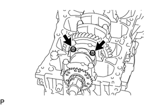
Remove the 2 connecting rod bolts and connecting rod cap.
Tech Tips
Keep the connecting rod bearing and connecting rod cap together.
-
Clean the crank pin and connecting rod bearing.
-
Check the crank pin and connecting rod bearing for pitting and scratches.
If the crank pin or connecting rod bearing is damaged, replace the connecting rod bearings. If necessary, replace the crankshaft.
-
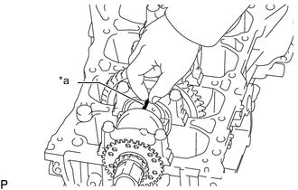
*a Plastigage Lay a strip of Plastigage on the crank pin.
-
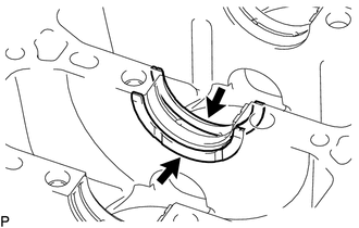
Install the connecting rod cap.
Note
Do not turn the crankshaft.
-
Remove the 2 connecting rod bolts and connecting rod cap.
Tech Tips
Keep the connecting rod bearing and connecting rod cap together.
-
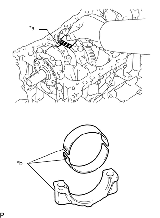
*a Plastigage *b Number Mark Measure the Plastigage at its widest point.
Standard Oil Clearance 0.035 to 0.068 mm (0.00138 to 0.00268 in.) Maximum Oil Clearance 0.07 mm (0.00276 in.) Note
Remove the Plastigage completely after the measurement.
If the oil clearance is more than the maximum, replace the connecting rod bearings. If necessary, replace the crankshaft.
Tech Tips
If replacing a connecting rod bearing, select a new one with the same number as marked on the connecting rod cap. There are 3 sizes of standard connecting rod bearings, marked "1", "2" or "3" accordingly.
Standard Crank Pin Diameter 51.492 to 51.500 mm (2.0272 to 2.0276 in.) Standard Connecting Rod Big End Inside Diameter Item Specified Condition Mark 1 54.500 to 54.508 mm (2.14567 to 2.14598 in.) Mark 2 54.509 to 54.516 mm (2.14602 to 2.14629 in.) Mark 3 54.517 to 54.524 mm (2.14633 to 2.14661 in.) Standard Size Bearing Center Wall Thickness Item Specified Condition Mark 1 1.486 to 1.490 mm (0.0585 to 0.0587 in.) Mark 2 1.491 to 1.494 mm (0.0587 to 0.0588 in.) Mark 3 1.495 to 1.498 mm (0.0589 to 0.0590 in.) -
Perform the inspection above for each cylinder.
-
-
REMOVE PISTON WITH CONNECTING ROD
-
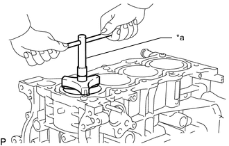
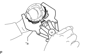
*a Ridge Reamer Using a ridge reamer, remove all the carbon from the top of the cylinder.
-
Remove the 8 connecting rod bolts and 4 connecting rod caps.
Tech Tips
Keep the connecting rod bearing and connecting rod cap together.
-
Push the piston with connecting rod and connecting rod bearing through the top of the cylinder block sub-assembly.
Tech Tips
-
Keep the connecting rod bearings, connecting rod and connecting rod cap together.
-
Arrange the removed parts in the correct order.
-
-
-
REMOVE CONNECTING ROD BEARING
-
Remove the connecting rod bearings from the connecting rods and connecting rod caps.
Tech Tips
Arrange the removed parts in the correct order.
-
-
INSPECT CRANKSHAFT THRUST CLEARANCE
-
Using a dial indicator, measure the crankshaft thrust clearance while prying the crankshaft back and forth with a screwdriver.
Standard Thrust Clearance 0.04 to 0.24 mm (0.00157 to 0.00945 in.) Maximum Thrust Clearance 0.30 mm (0.0118 in.) If the crankshaft thrust clearance is more than the maximum, replace the crankshaft thrust washers as a set. If necessary, replace the crankshaft.
Standard Thrust Washer Thickness 1.93 to 1.98 mm (0.0760 to 0.0780 in.)
-
-
REMOVE CRANKSHAFT
-
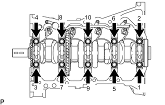
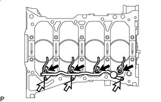
Uniformly loosen and remove the 10 crankshaft bearing cap bolts in several steps in the order shown in the illustration.
-
Remove the 5 crankshaft bearing caps from the cylinder block sub-assembly.
Tech Tips
-
Keep the No. 2 crankshaft bearings and crankshaft bearing caps together.
-
Arrange the removed parts in such a way that they can be reinstalled to their original locations.
-
-
Remove the crankshaft from the cylinder block sub-assembly.
Tech Tips
Keep the crankshaft bearings and crankshaft thrust washers together with the cylinder block sub-assembly.
-
Check each crankshaft journal and crankshaft bearing for pitting and scratches.
If the crankshaft journal or crankshaft bearing is damaged, replace the crankshaft bearings. If necessary, replace the crankshaft.
-
-
REMOVE CRANKSHAFT THRUST WASHER
-
Remove the 2 crankshaft thrust washers from the cylinder block sub-assembly.
-
-
REMOVE CRANKSHAFT BEARING
-
Remove the crankshaft bearings and No. 2 crankshaft bearings from the cylinder block sub-assembly and crankshaft bearing caps.
Tech Tips
Arrange the removed parts in such a way that they can be reinstalled to their original locations.
-
-
REMOVE CRANKSHAFT PULLEY SET KEY
-
Using a screwdriver, remove the 2 crankshaft pulley set keys from the crankshaft.
-
-
REMOVE PISTON RING SET
-
*a Piston Ring Expander Using a piston ring expander, remove the No. 1 compression ring and No. 2 compression ring.
-
Remove the oil ring expander, upper side rail and lower side rail by hand.
Tech Tips
Arrange the removed parts in such a way that they can be reinstalled to their original locations.
-
-
REMOVE PISTON PIN HOLE SNAP RING
-
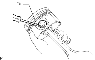
*a Protective Tape Using a small screwdriver with its tip wrapped with protective tape, pry out the piston pin hole snap ring (front side).
Note
-
Do not remove the piston pin hole snap ring (rear side) unless necessary.
-
-
-
REMOVE PISTON
-
Gradually heat each piston to between 80 and 90°C (176 and 194°F).
-
Using a hammer and brass bar, lightly tap out the piston pin. Then remove the connecting rod sub-assembly.
Tech Tips
-
The piston and piston pin are a matched set.
-
Arrange the removed parts in such a way that they can be reinstalled to their original locations.
-
-
-
REMOVE OIL PIPE SUB-ASSEMBLY
-

Hexagon Socket Head Cap Bolt 
Bolt Using a 5 mm hexagon socket wrench, remove the 4 hexagon socket head cap bolts.
-
Remove the 3 bolts and oil pipe sub-assembly from the cylinder block sub-assembly.
-
Remove the oil pipe gasket from the oil pipe sub-assembly.
-
-
REMOVE STUD BOLT
Note
If a stud bolt is deformed or its threads are damaged, replace it.