ENGINE UNIT REMOVAL

CAUTION / NOTICE / HINT
The necessary procedures (adjustment, calibration, initialization, or registration) that must be performed after parts are removed and installed, or replaced during engine unit removal/installation are shown below.
| Replaced Part or Performed Procedure | Necessary Procedure | Effect/Inoperative Function when Necessary Procedure not Performed | Link | |
|---|---|---|---|---|
| Battery terminal is disconnected/reconnected | Memorize steering angle neutral point | LKA/LDA System | ||
| Pre-crash safety system | ||||
| Lighting system (EXT)
|
||||
| Adaptive high beam system | ||||
| Drive the vehicle until stop and start control is permitted (approximately 15 to 60 minutes) | Stop and start system | |||
| Memorize steering angle neutral point | Parking Assist Monitor System (w/ Parallel Parking Assist Function) | |||
| Parking Assist Monitor System (w/o Parallel Parking Assist Function) | ||||
| Panoramic view monitor system | ||||
| Initialize back door lock | Power door lock control system | |||
| Reset back door close position | Power back door system | |||
| Replacement of ECM | Perform Vehicle Identification Number (VIN) or frame number registration |
|
||
| ECU Communication ID Registration (Immobiliser system) | Engine start function | See Service Bulletin for the registration method. | ||
|
Inspection After Repair |
|
||
| Replacement of starter assembly*1 Note When the starter assembly is replaced, "ST relay" and "ST NO. 2 relay" must be also replaced. |
Clear Number of Starter Operations | Stop and start system | ||
| Replacement of battery*1 |
|
|||
|
Bleed the oil pump assembly with motor (continuously variable transaxle assembly) | |||
| Replacement of automatic transaxle assembly | Perform the following procedures in the order shown:
|
|
Click here for Initialization (U661E) Click here for Registration (U661E) Click here for Initialization (U661F) Click here for Registration (U661F) |
|
| Replacement of ECM (If possible, read the transaxle compensation code from the previous ECM) |
Possible to read transaxle compensation code | Perform the following procedures in the order shown:
|
||
| Impossible to read transaxle compensation code | Perform the following procedures in the order shown:
|
|||
| Suspension, tires, etc.*2 | Rear television camera assembly optical axis (Back camera position setting) | Parking assist monitor system (w/ Parallel Parking Assist Function) | Click here for Initialization Click here for Calibration |
|
| Parking assist monitor system (w/o parallel parking assist function) | Click here for Initialization Click here for Calibration |
|||
|
Panoramic view monitor system | Click here for Initialization Click here for Calibration |
||
| Initialize headlight ECU sub-assembly LH |
|
|||
| Front wheel alignment adjustment |
|
|
||
*2: The vehicle height changes because of suspension or tire replacement
*3: w/ TFT Meter Type
PROCEDURE
-
PRECAUTION
CAUTION:
-
The exhaust valve is filled with sodium. Sodium is a strong alkali which can produce a dangerous chemical reaction. Be very careful when handling and disposing of it.
-
Do not intentionally expose the sodium in exhaust valve. If sodium enters your eyes, vision loss may occur. If sodium contacts your skin, burns may occur. If a fire occurs due to a chemical reaction with sodium, burns may occur.
-
If the sodium in the exhaust valve is exposed, perform all necessary preparations to safely remove and dispose of the sodium.
-
When removing a damaged exhaust valve, always wear rubber gloves and safety glasses.
-
Do not intentionality cut or break open the exhaust valve to remove the sodium.
Tech Tips
-
The sodium inside the exhaust valve is safe as long as it remains sealed inside the exhaust valve.
-
Exhaust valves filled with sodium can be identified by their "NA" identification mark.
-
Removal of the exhaust valve:
-
Disposal of the exhaust valve:
-
-
REMOVE DRIVE SHAFT BEARING BRACKET (for 2WD)
-
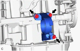
Remove the 3 bolts and drive shaft bearing bracket from the cylinder block sub-assembly and stiffening crankcase assembly.
-
-
REMOVE NO. 2 TRANSFER STIFFENER PLATE (for AWD)
-
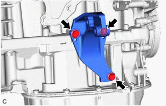
Remove the 3 bolts and No. 2 transfer stiffener plate from the cylinder block sub-assembly and stiffening crankcase assembly.
-
-
REMOVE V-RIBBED BELT
-
REMOVE GENERATOR ASSEMBLY
-
REMOVE COMPRESSOR ASSEMBLY WITH PULLEY
-
REMOVE NO. 1 COMPRESSOR MOUNTING BRACKET
-
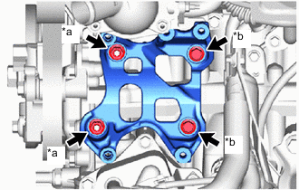
*a Nut *b Bolt Remove the 2 bolts, 2 nuts and No. 1 compressor mounting bracket.
-
Using E8 "TORX" socket wrench, remove the 2 stud bolts from the cylinder block sub-assembly and stiffening crankcase assembly.
-
-
DISCONNECT ENGINE WIRE
-
REMOVE NO. 2 WATER BY-PASS PIPE
-
REMOVE PURGE VALVE (PURGE VSV)
-
DISCONNECT NO. 2 VACUUM TRANSMITTING HOSE ASSEMBLY
-
DISCONNECT VACUUM TRANSMITTING HOSE ASSEMBLY
-
DISCONNECT NO. 1 WATER BY-PASS HOSE AND NO. 2 WATER BY-PASS HOSE
-
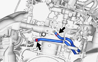
Slide the clamp and disconnect the No. 1 water by-pass hose from the cylinder head sub-assembly.
-
Slide the clamp and disconnect the No. 2 water by-pass hose from the No. 1 water by-pass pipe.
-
-
REMOVE NO. 2 VENTILATION HOSE
-
REMOVE FUEL PUMP PROTECTOR
-
REMOVE STUD BOLT
-
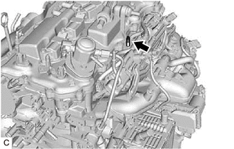
Using an E8 "TORX" socket wrench, remove the stud bolt.
-
-
REMOVE INTAKE MANIFOLD WITH INTERCOOLER ASSEMBLY AND THROTTLE WITH MOTOR BODY ASSEMBLY
-
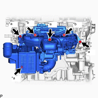
*a Bolt *b Nut Remove the 4 bolts, 2 nuts, intake manifold with intercooler assembly and throttle with motor body assembly.
-
Remove the 2 No. 1 intake manifold to head gaskets from the intake manifold.
-
-
REMOVE IGNITION COIL ASSEMBLY
-
REMOVE NO. 1 EXHAUST MANIFOLD HEAT INSULATOR
-
REMOVE NO. 2 EXHAUST MANIFOLD HEAT INSULATOR
-
REMOVE EXHAUST MANIFOLD CONVERTER SUB-ASSEMBLY (TWC: Front Catalyst)
-
DISCONNECT INLET TURBO OIL PIPE SUB-ASSEMBLY
-
REMOVE TURBOCHARGER SUB-ASSEMBLY
-
REMOVE ENGINE WIRE
-
Remove the engine wire from the engine assembly with transaxle.
-
-
REMOVE WIRE HARNESS CLAMP BRACKET
-
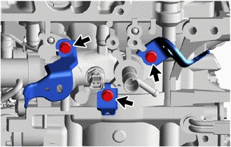
Remove the 3 bolts and 3 wire harness clamp brackets from the cylinder head sub-assembly.
-
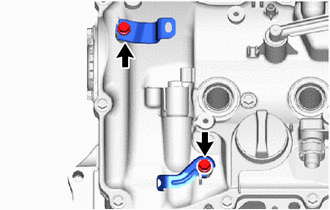
Remove the 2 bolts and 2 wire harness clamp brackets from the cylinder head cover sub-assembly.
-
-
REMOVE OIL FILLER CAP SUB-ASSEMBLY
-
Remove the oil filler cap sub-assembly from the cylinder head cover sub-assembly.
-
-
REMOVE OIL FILLER CAP GASKET
-
Remove the oil filler cap gasket from the oil filler cap sub-assembly.
-
-
REMOVE V-RIBBED BELT TENSIONER ASSEMBLY
-
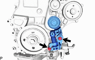
Remove the 2 bolts and V-ribbed belt tensioner assembly from the timing chain cover assembly.
-
-
REMOVE IDLER PULLEY SUB-ASSEMBLY
-
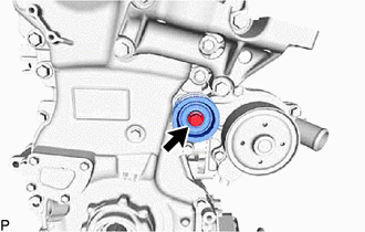
Remove the bolt and idler pulley sub-assembly from the timing chain cover assembly.
-