ENGINE ASSEMBLY REMOVAL

CAUTION / NOTICE / HINT
The necessary procedures (adjustment, calibration, initialization, or registration) that must be performed after parts are removed and installed, or replaced during engine assembly removal/installation are shown below.
| Replaced Part or Performed Procedure | Necessary Procedure | Effect/Inoperative Function when Necessary Procedure not Performed | Link | |
|---|---|---|---|---|
| Battery terminal is disconnected/reconnected | Memorize steering angle neutral point | LKA/LDA System | ||
| Pre-crash safety system | ||||
| Lighting system (EXT)
|
||||
| Adaptive high beam system | ||||
| Drive the vehicle until stop and start control is permitted (approximately 15 to 60 minutes) | Stop and start system | |||
| Memorize steering angle neutral point | Parking Assist Monitor System (w/ Parallel Parking Assist Function) | |||
| Parking Assist Monitor System (w/o Parallel Parking Assist Function) | ||||
| Panoramic view monitor system | ||||
| Initialize back door lock | Power door lock control system | |||
| Reset back door close position | Power back door system | |||
| Replacement of ECM | Perform Vehicle Identification Number (VIN) or frame number registration |
|
||
| ECU Communication ID Registration (Immobiliser system) | Engine start function | See Service Bulletin for the registration method. | ||
|
Inspection After Repair |
|
||
| Replacement of starter assembly*1 Note When the starter assembly is replaced, "ST relay" and "ST NO. 2 relay" must be also replaced. |
Clear Number of Starter Operations | Stop and start system | ||
| Replacement of battery*1 |
|
|||
|
Bleed the oil pump assembly with motor (continuously variable transaxle assembly) | |||
| Replacement of automatic transaxle assembly | Perform the following procedures in the order shown:
|
|
Click here for Initialization (U661E) Click here for Registration (U661E) Click here for Initialization (U661F) Click here for Registration (U661F) |
|
| Replacement of ECM (If possible, read the transaxle compensation code from the previous ECM) |
Possible to read transaxle compensation code | Perform the following procedures in the order shown:
|
||
| Impossible to read transaxle compensation code | Perform the following procedures in the order shown:
|
|||
| Suspension, tires, etc.*2 | Rear television camera assembly optical axis (Back camera position setting) | Parking assist monitor system (w/ Parallel Parking Assist Function) | Click here for Initialization Click here for Calibration |
|
| Parking assist monitor system (w/o parallel parking assist function) | Click here for Initialization Click here for Calibration |
|||
|
Panoramic view monitor system | Click here for Initialization Click here for Calibration |
||
| Initialize headlight ECU sub-assembly LH |
|
|||
| Front wheel alignment adjustment |
|
|
||
*2: The vehicle height changes because of suspension or tire replacement
*3: w/ TFT Meter Type
CAUTION:
-
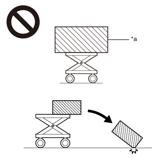
*a An Object Exceeding Weight Limit of Engine Lifter The engine assembly with transaxle is very heavy. Be sure to follow the procedure described in the repair manual, or the engine lifter may suddenly drop or the engine assembly with transaxle may fall off the engine lifter.
-
To prevent burns, do not touch the engine, exhaust manifold or other high temperature components while the engine is hot.
PROCEDURE
-
RECOVER REFRIGERANT FROM REFRIGERATION SYSTEM
for HFC-134a (R134a): Click here
for HFO-1234yf (R1234yf): Click here
-
DISCHARGE FUEL SYSTEM PRESSURE
-
ALIGN FRONT WHEELS FACING STRAIGHT AHEAD
-
SECURE STEERING WHEEL
-
PRECAUTION
Note
After turning the engine switch off, waiting time may be required before disconnecting the cable from the battery terminal. Therefore, make sure to read the disconnecting the cable from the battery terminal notice before proceeding with work.
-
DISCONNECT CABLE FROM NEGATIVE BATTERY TERMINAL
Note
When disconnecting the cable, some systems need to be initialized after the cable is reconnected.
-
REMOVE FRONT WHEELS
-
REMOVE FRONT WHEEL OPENING EXTENSION PAD LH
-
Remove the 2 screws and front wheel opening extension pad LH.
-
-
REMOVE FRONT WHEEL OPENING EXTENSION PAD RH
-
Remove the 2 screws and front wheel opening extension pad RH.
-
-
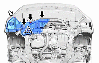
REMOVE NO. 3 ENGINE UNDER COVER
-


Bolt 
Screw Remove the 5 bolts, 2 screws, 2 clips and No. 3 engine under cover.
-
-
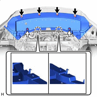
REMOVE NO. 1 ENGINE UNDER COVER
-
Bolt Screw Remove the 3 bolts, 2 screws, clip and No. 1 engine under cover.
-
-
REMOVE FRONT LOWER BUMPER ABSORBER
-
Screw Clip Remove the 4 screws, 2 clips and disengage the 2 claws to remove the front lower bumper absorber.
-
-
REMOVE FRONT FENDER APRON SEAL LH
-
Remove the 2 screws, clip and front fender apron seal LH.
-
-
REMOVE FRONT FENDER APRON SEAL RH
-
Remove the 2 screws, clip and front fender apron seal RH.
-
-
REMOVE NO. 2 ENGINE UNDER COVER
-
Bolt Screw Remove the 2 bolts, 2 screws, clip and No. 2 engine under cover.
-
-
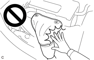
REMOVE FRONT FLOOR COVER LH
-
DRAIN ENGINE COOLANT
-
DRAIN COOLANT (for Intercooler)
-
DRAIN ENGINE OIL
-
DRAIN TRANSFER OIL (for AWD)
-
DRAIN AUTOMATIC TRANSAXLE FLUID
for 2WD: Click here
for AWD: Click here
-
REMOVE COOL AIR INTAKE DUCT SEAL
-
REMOVE NO. 1 ENGINE COVER SUB-ASSEMBLY
-
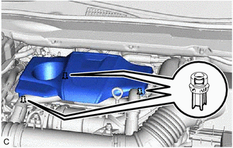
Disengage the 3 clips and No. 1 engine cover sub-assembly.
Note
When removing the No. 1 engine cover sub-assembly, make sure to lift it upward. Pulling the No. 1 engine cover sub-assembly towards you may damage the No. 1 engine cover sub-assembly.
-
-
REMOVE BATTERY
-
REMOVE BATTERY CARRIER SUB-ASSEMBLY
-
w/ NO. 3 Battery Clamp:
-
Disengage the 3 clamps and disconnect the wire harness from the battery carrier sub-assembly.
-
Remove the 2 bolts and No. 3 battery clamp.
-
Remove the 4 bolts and battery carrier sub-assembly.
-
-
w/o NO. 3 Battery Clamp
-

Disengage the 3 clamps and disconnect the wire harness from the battery carrier sub-assembly.
-
Remove the 6 bolts and battery carrier sub-assembly.
-
-
-
REMOVE BATTERY BRACKET REINFORCEMENT
-
Remove the 2 bolts and battery bracket reinforcement.
-
-
REMOVE INLET AIR CLEANER ASSEMBLY
-
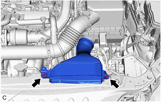
Remove the 2 bolts and inlet air cleaner assembly.
-
-
REMOVE AIR CLEANER CAP WITH AIR CLEANER HOSE
-
REMOVE AIR CLEANER FILTER ELEMENT SUB-ASSEMBLY
-
REMOVE AIR CLEANER CASE SUB-ASSEMBLY
-
REMOVE AIR CLEANER BRACKET
-
REMOVE ECM
-
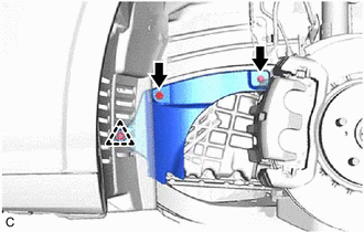
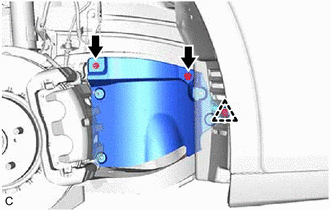
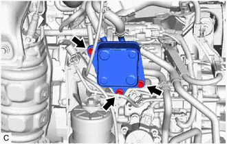
REMOVE INTERCOOLER RESERVE TANK ASSEMBLY
-
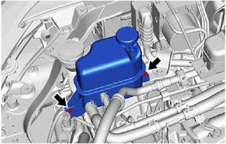
Remove the 2 bolts.
-
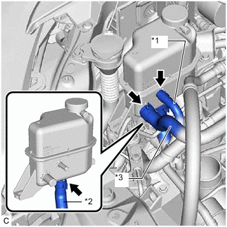
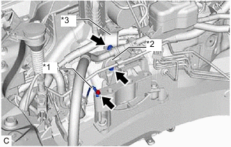
*1 No. 1 Turbo Water Hose *2 No. 1 Intercooler Cooling Water Hose *3 No. 4 Intercooler Cooling Water Hose Slide the clip and disconnect the No. 1 turbo water hose from the intercooler reserve tank assembly.
-
Slide the clip and disconnect the No. 4 intercooler cooling water hose from the intercooler reserve tank assembly.
-
Slide the clip, disconnect the No. 1 intercooler cooling water hose from the intercooler reserve tank assembly and remove the intercooler reserve tank assembly.
-
-
REMOVE INTAKE AIR CONNECTOR
-
REMOVE NO. 2 AIR CLEANER HOSE
-
REMOVE NO. 5 EXHAUST MANIFOLD HEAT INSULATOR
-
REMOVE OUTLET COMPRESSOR ELBOW
-
REMOVE INTAKE AIR RESONATOR
-
REMOVE NO. 1 AIR TUBE
-
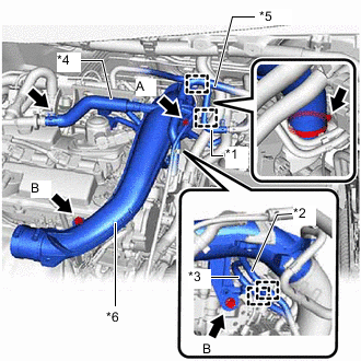
*1 No. 2 Fuel Vapor Feed Hose *2 Fuel Tube Sub-assembly *3 No. 2 Fuel Tube Sub-assembly *4 No. 3 Ventilation Hose *5 Vacuum Switching Valve Hose Assembly *6 No. 1 Air Tube Disengage the 2 clamps to disconnect the No. 2 fuel vapor feed hose from the No. 1 air tube.
-
Disengage the 2 clamps to disconnect the fuel tube sub-assembly and No. 2 fuel tube sub-assembly from the No. 1 air tube.
-
Slide the clip and disconnect the No. 3 ventilation hose from the No. 1 air tube.
-
Remove the bolt (A) and disconnect the vacuum switching valve hose assembly from the No. 1 air tube.
-
Remove the 2 bolts (B).
-
Loosen the clamp, then remove the No. 1 air tube from the intercooler assembly.
-
-
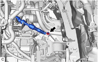
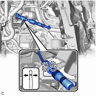
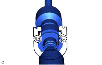
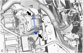
SEPARATE NO. 3 INTERCOOLER COOLING WATER HOSE
-
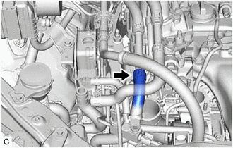
Slide the clip and disconnect the No. 3 intercooler cooling water hose from the No. 3 intercooler cooling water pipe.
-
-
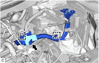
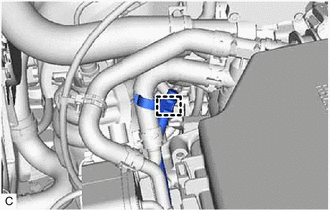
DISCONNECT NO. 2 RADIATOR HOSE
-
Slide the clip and disconnect the No. 2 radiator hose from the water inlet.
-
-
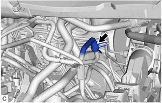
DISCONNECT NO. 1 RADIATOR HOSE
-
Slide the clip and disconnect the No. 1 radiator hose from the cylinder head sub-assembly.
-
-
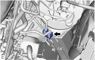
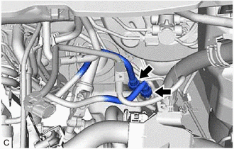
DISCONNECT HEATER HOSE
-
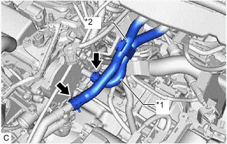
*1 Inlet Heater Hose *2 Outlet Heater Hose Slide the clip and disconnect the inlet heater hose from the cylinder head sub-assembly.
-
Slide the clip and disconnect the outlet heater hose from the water hose sub-assembly.
-
-
DISCONNECT SUCTION HOSE SUB-ASSEMBLY
-
DISCONNECT DISCHARGE HOSE SUB-ASSEMBLY
-
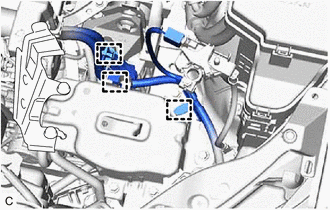
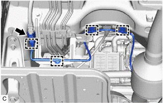
DISCONNECT ENGINE WIRE
-
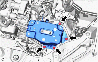
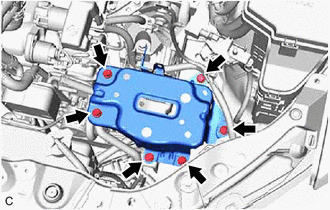
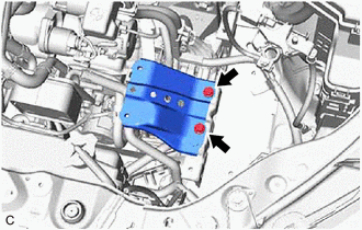
Remove the engine room relay block assembly.
-
Remove the nut, disengage the 2 engine wire clamps and disconnect the engine wire.
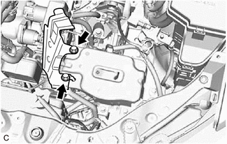
-
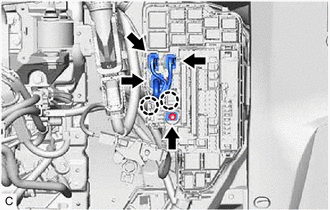
Remove the nut from the No. 1 engine room relay block and No. 1 junction block assembly.
-
Disconnect the 3 connectors from the No. 1 engine room relay block and No. 1 junction block assembly.
-
Disengage the 2 claws to disconnect the engine wire from the No. 1 engine room relay block and No. 1 junction block assembly.
-
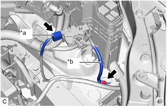
*a Battery State Sensor Assembly Connector *b Earth Wire Disconnect the battery state sensor assembly connector.
-
Remove the bolt and disconnect the earth wire.
-
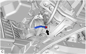
Remove the bolt and disconnect the No. 2 earth wire from the compressor assembly with pulley.
-
-
REMOVE STARTER ASSEMBLY
-
DISCONNECT UNION TO CHECK VALVE HOSE (for LHD)
-
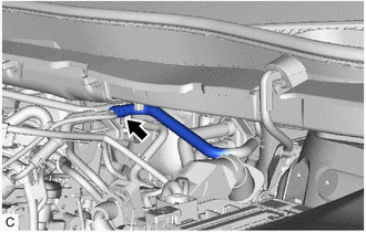
Slide the clip and disconnect the union to check valve hose from the vacuum switching valve hose assembly.
-
-
DISCONNECT UNION TO CONNECTOR TUBE HOSE (for RHD)
-
Slide the clip and disconnect the union to connector tube hose from the vacuum switching valve hose assembly.
-
-
DISCONNECT NO. 1 FUEL HOSE
-
Remove the No. 2 fuel pipe clamp from the fuel tube connector.
-
Disconnect the No. 1 fuel hose from the 2 fuel pipes.
-
-
DISCONNECT FUEL VAPOR FEED HOSE ASSEMBLY
-
Slide the clip and disconnect the fuel vapor feed hose assembly from the fuel pipe.
-
-
DISCONNECT TRANSMISSION OIL COOLER
-
Disengage the clamp and No. 1 breather plug (ATM) from the breather plug hose clamp.
-
Disconnect the 3 bolts and disconnect the transmission oil cooler from the front engine mounting bracket.
-
-
REMOVE TRANSMISSION OIL THERMOSTAT
for 2WD: Click here
for AWD: Click here
-
DISCONNECT TRANSMISSION CONTROL CABLE ASSEMBLY
-
Remove the nut and disconnect the transmission control cable assembly from the control shift lever.
-
Using a screwdriver, disengage the 4 claws and disconnect the transmission control cable assembly with clip from the No. 1 transmission control cable bracket.
-
Using a screwdriver, disengage the 2 claws and remove the clip from the transmission control cable assembly.
-
-
REMOVE FRONT EXHAUST PIPE ASSEMBLY
-
REMOVE CENTER EXHAUST PIPE ASSEMBLY (TWC: Rear Catalyst)
CAUTION:
To prevent burns, do not touch the engine, exhaust pipe or other high temperature components while the engine is hot.
-
Disconnect the heated oxygen sensor connector.
-
Disengage the 3 wire harness clamps.
-
Remove the 2 bolts and 2 compression springs and disconnect the tail exhaust pipe assembly from the center exhaust pipe assembly (TWC: Rear Catalyst).
-
Remove the exhaust pipe gasket from the center exhaust pipe assembly (TWC: Rear Catalyst).
-
Remove the center exhaust pipe assembly (TWC: Rear Catalyst) from the 2 exhaust pipe supports.
-
-
SEPARATE STEERING INTERMEDIATE SHAFT ASSEMBLY
-
REMOVE FRONT DRIVE SHAFT ASSEMBLY
-
REMOVE PROPELLER SHAFT WITH CENTER BEARING ASSEMBLY (for AWD)
-
REMOVE FLYWHEEL HOUSING UNDER COVER
-
Remove the flywheel housing under cover from the engine assembly.
-
-
REMOVE DRIVE PLATE AND TORQUE CONVERTER ASSEMBLY SETTING BOLT
for 2WD: Click here
for AWD: Click here
-
REMOVE ENGINE ASSEMBLY WITH TRANSAXLE
-
Using height adjustment attachments and plate lift attachments to keep the engine assembly with transaxle level, set an engine lifter underneath the engine assembly with transaxle.
Note
-
Do not perform any procedures while the engine assembly is suspended because doing so may cause the engine assembly to drop, resulting in injury. However, the engine assembly needs to be suspended when it is installed to or removed from an engine stand.
-
To prevent the engine assembly from unexpectedly moving, securely support the engine assembly until it is secured to an engine stand.
-
-
Remove the bolt, nut and disconnect the engine mounting insulator LH from the engine mounting bracket LH.
-
Type A:
-
Remove the 2 bolts, 2 nuts and disconnect the engine mounting insulator sub-assembly RH from the engine mounting bracket RH.
-
-
Type B:
-
Remove the bolt, 3 nuts and disconnect the engine mounting insulator sub-assembly RH from the engine mounting bracket RH.
-
-
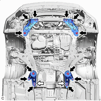
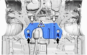
Bolt Nut Remove the 6 bolts, 2 nuts and frame side rail plate sub-assembly RH and front suspension member bracket sub-assembly RH.
-
Remove the 6 bolts, 2 nuts and frame side rail plate sub-assembly LH and front suspension member bracket sub-assembly LH.
-
Operate the engine lifter to remove the engine assembly with transaxle from the vehicle.
Note
-
Make sure that the engine assembly with transaxle is clear of all wirings and hoses.
-
While lowering the engine assembly with transaxle from the vehicle, do not allow it to contact the vehicle.
-
-
-
INSTALL ENGINE HANGER
-
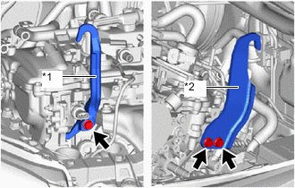
*1 No. 1 Engine Hanger *2 No. 2 Engine Hanger Install the No. 1 engine hanger and No. 2 engine hanger with the 3 bolts as shown in the illustration.
- Torque:
- 43 N*m { 438 kgf*cm, 32 ft.*lbf }
Tech Tips
No. 1 Engine Hanger 12281-36100 No. 2 Engine Hanger 12282-36100
12282-36101
Bolt (No. 1 Engine Hanger) 91552-81050 Bolt (No. 2 Engine Hanger) 91552-81025 -
Using an engine sling device and engine lift, secure the engine assembly with transaxle.
Note
-
Pay attention to the angle of the sling device as the engine assembly or No. 1 engine hanger and No. 2 engine hanger may be damaged or deformed if the angle is incorrect.
-
Do not perform any procedures while the engine assembly is suspended because doing so may cause the engine assembly to drop, resulting in injury. However, the engine assembly needs to be suspended when it is installed to or removed from an engine stand.
-
-
-
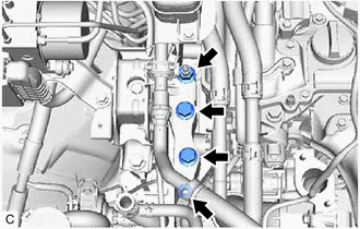
REMOVE NO. 3 INTERCOOLER COOLING WATER PIPE
-
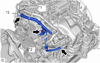
*1 No. 5 Intercooler Cooling Water Hose *2 No. 2 Intercooler Cooling Water Hose *3 No. 2 Water By-pass Pipe Slide the clip and disconnect the No. 5 intercooler cooling water hose from the No. 2 water by-pass pipe.
-
Slide the clip and disconnect the No. 2 intercooler cooling water hose from the No. 1 turbo water pipe sub-assembly.
-
Remove the bolt and No. 3 intercooler cooling water pipe from the engine assembly.
-
-
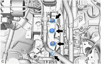
REMOVE NO. 2 INTERCOOLER COOLING WATER PIPE
-
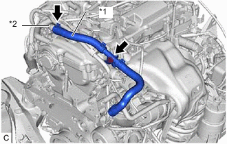
*1 No. 6 Intercooler Cooling Water Hose *2 No. 2 Water By-pass Pipe Slide the clip and disconnect the No. 6 intercooler cooling water hose from the No. 2 water by-pass pipe.
-
Remove the bolt and No. 2 intercooler cooling water pipe from the engine assembly.
-
-
DISCONNECT WIRE HARNESS
for 2WD: Click here
for AWD: Click here
-
REMOVE FRONT NO. 1 STABILIZER BRACKET LH
-
REMOVE FRONT NO. 1 STABILIZER BRACKET RH
Tech Tips
Perform the same procedure as for the LH side.
-
REMOVE FRONT STABILIZER BAR
-
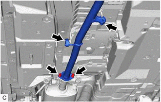
REMOVE STEERING LINK ASSEMBLY
-
REMOVE TRANSFER STIFFENER PLATE RH (for AWD)
-
REMOVE FRONT FRAME ASSEMBLY
-
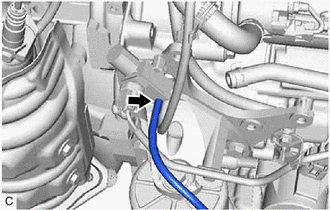
Disconnect the vacuum hose from the vacuum switching valve assembly.
-
Remove the bolt and separate the front engine mounting insulator from the front engine mounting bracket.
-
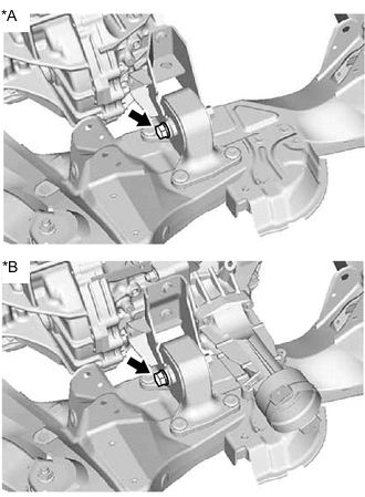
*A for 2WD *B for AWD Remove the bolt and separate the rear engine mounting insulator with the front frame assembly from the rear engine mounting bracket.
-
-
REMOVE AUTOMATIC TRANSAXLE ASSEMBLY
for 2WD: Click here
for AWD: Click here
-
REMOVE DRIVE PLATE AND RING GEAR SUB-ASSEMBLY
-
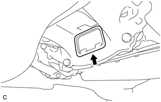
REMOVE FRONT ENGINE MOUNTING INSULATOR
Tech Tips
Perform this procedure only when replacement of the front engine mounting insulator is necessary.
-
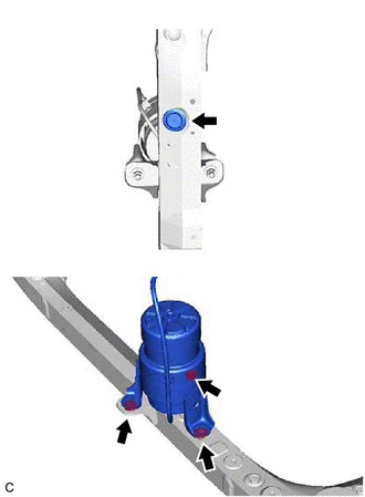
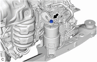
Remove the hole plug from the front frame assembly.
-
Remove the 3 nuts and front engine mounting insulator from the front frame assembly.
-
-
REMOVE REAR ENGINE MOUNTING INSULATOR
Tech Tips
Perform this procedure only when replacement of the rear engine mounting insulator is necessary.
-
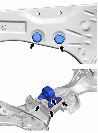
Remove the 2 hole plugs from the front frame assembly.
-
Remove the 4 nuts and rear engine mounting insulator.
-
-
REMOVE ENGINE MOUNTING INSULATOR SUB-ASSEMBLY RH
Tech Tips
Perform this procedure only when replacement of the engine mounting insulator sub-assembly RH is necessary.
-
*1 Earth Wire *2 Cooler Compressor Bracket *3 Brake Actuator with Bracket Remove the bolt and earth wire from the engine mounting insulator sub-assembly RH.
-
Remove the bolt and cooler compressor bracket from the engine mounting insulator sub-assembly RH.
-
Remove the bolt and brake actuator with bracket from the vehicle body.
-
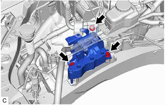
Remove the 2 bolts, nut and engine mounting insulator sub-assembly RH from the vehicle body.
-
-
REMOVE ENGINE MOUNTING SPACER
Tech Tips
Perform this procedure only when replacement of the engine mounting spacer is necessary.
-
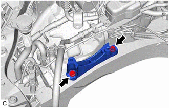
Remove the 2 bolts and engine mounting spacer.
-
-
REMOVE ENGINE MOUNTING INSULATOR LH
Tech Tips
Perform this procedure only when replacement of the engine mounting insulator LH is necessary.
-
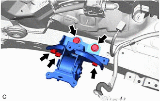
Remove the 5 bolts and engine mounting insulator LH from the vehicle body.
-
-
INSTALL ENGINE TO ENGINE STAND
-
Install the engine to an engine stand.
-
-
REMOVE ENGINE HANGERS
-
Remove the 3 bolts, No. 1 engine hanger and No. 2 engine hanger.
-