CYLINDER HEAD GASKET REMOVAL
CAUTION / NOTICE / HINT
The necessary procedures (adjustment, calibration, initialization, or registration) that must be performed after parts are removed and installed, or replaced during cylinder head gasket removal/installation are shown below.
| Replaced Part or Performed Procedure | Necessary Procedure | Effect/Inoperative Function when Necessary Procedure not Performed | Link | |
|---|---|---|---|---|
| Battery terminal is disconnected/reconnected | Memorize steering angle neutral point | LKA/LDA System | ||
| Intelligent clearance sonar system*4 | ||||
| Pre-crash safety system | ||||
| Lighting system (EXT)
|
||||
| Adaptive high beam system | ||||
| Drive the vehicle until stop and start control is permitted (approximately 15 to 60 minutes) | Stop and start system | |||
| Memorize steering angle neutral point | Parking Assist Monitor System (w/ Parallel Parking Assist Function) | |||
| Parking Assist Monitor System (w/o Parallel Parking Assist Function) | ||||
| Panoramic view monitor system | ||||
| Initialize back door lock | Power door lock control system | |||
| Reset back door close position | Power back door system | |||
| Replacement of ECM | Perform Vehicle Identification Number (VIN) or frame number registration |
|
||
| ECU Communication ID Registration (Immobiliser system) | Engine start function | See Service Bulletin for the registration method. | ||
| Replacement of ECM (If possible, read the transaxle compensation code from the previous ECM) |
Possible to read transaxle compensation code | Perform the following procedures in the order shown:
|
|
Click here for Initialization (U661E) Click here for Registration (U661E) Click here for Initialization (U661F) Click here for Registration (U661F) |
| Impossible to read transaxle compensation code | Perform the following procedures in the order shown:
|
|||
|
Inspection After Repair |
|
||
| Replacement of starter assembly*1 Note When the starter assembly is replaced, "ST relay" and "ST NO. 2 relay" must be also replaced. |
Clear Number of Starter Operations | Stop and start system | ||
| Replacement of battery*1 |
|
|||
|
Bleed the oil pump assembly with motor (continuously variable transaxle assembly) | |||
| Replacement of automatic transaxle assembly | Perform the following procedures in the order shown:
|
|
Click here for Initialization (U661E) Click here for Registration (U661E) Click here for Initialization (U661F) Click here for Registration (U661F) |
|
| Suspension, tires, etc.*2 |
|
|
||
| Rear television camera assembly optical axis (Back camera position setting) | Parking assist monitor system (w/ Parallel Parking Assist Function) | Click here for Initialization Click here for Calibration |
||
| Parking assist monitor system (w/o parallel parking assist function) | Click here for Initialization Click here for Calibration |
|||
|
Panoramic view monitor system | Click here for Initialization Click here for Calibration |
||
| Initialize headlight ECU sub-assembly LH |
|
|||
| Front wheel alignment adjustment |
|
|
||
*2: The vehicle height changes because of suspension or tire replacement
*3: w/ TFT Meter Type
*4: When performing learning using the GTS.
Click here Click here
PROCEDURE
-
REMOVE TIMING CHAIN COVER ASSEMBLY
-
REMOVE PURGE VALVE (PURGE VSV)
-
DISCONNECT NO. 1 WATER BY-PASS HOSE AND NO. 2 WATER BY-PASS HOSE
-
REMOVE INTAKE MANIFOLD WITH INTERCOOLER ASSEMBLY AND THROTTLE WITH MOTOR BODY ASSEMBLY
-
DISCONNECT NO. 6 ENGINE WIRE (for Port Injection)
-
REMOVE FUEL DELIVERY PIPE (for Port Injection)
-
REMOVE PORT FUEL INJECTOR ASSEMBLY (for Port Injection)
-
DISCONNECT SENSOR WIRE (for Direct Injection)
-
REMOVE FUEL DELIVERY PIPE SUB-ASSEMBLY (for Direct Injection)
-
REMOVE DIRECT FUEL INJECTOR ASSEMBLY (for Direct Injection)
-
REMOVE FUEL INJECTOR SEAL (for Direct Injection)
-
REMOVE NO. 1 EXHAUST MANIFOLD HEAT INSULATOR
-
REMOVE NO. 2 EXHAUST MANIFOLD HEAT INSULATOR
-
REMOVE EXHAUST MANIFOLD CONVERTER SUB-ASSEMBLY (TWC: Front Catalyst)
-
DISCONNECT INLET TURBO OIL PIPE SUB-ASSEMBLY
-
REMOVE TURBOCHARGER SUB-ASSEMBLY
-
REMOVE VACUUM PUMP ASSEMBLY
-
REMOVE ENGINE OIL LEVEL DIPSTICK GUIDE
-
SET NO. 1 CYLINDER TO TDC/COMPRESSION
-
REMOVE NO. 1 CHAIN TENSIONER ASSEMBLY
-
REMOVE TIMING CHAIN GUIDE
-
REMOVE CHAIN TENSIONER SLIPPER
-
REMOVE CHAIN SUB-ASSEMBLY
-
REMOVE NO. 1 CHAIN VIBRATION DAMPER
-
REMOVE CAMSHAFT TIMING GEAR ASSEMBLY
-
REMOVE CAMSHAFT TIMING EXHAUST GEAR ASSEMBLY
-
REMOVE CAMSHAFT HOUSING SUB-ASSEMBLY
-
REMOVE NO. 3 WATER BY-PASS PIPE
-
DISCONNECT NO. 7 WATER BY-PASS HOSE
-
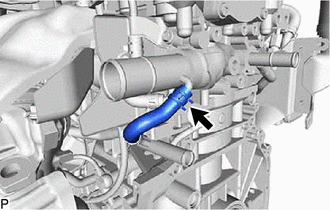
Slide the clip and disconnect the No. 7 water by-pass hose from the cylinder head sub-assembly.
-
-
REMOVE NO. 1 VALVE ROCKER ARM SUB-ASSEMBLY
-
REMOVE VALVE LASH ADJUSTER ASSEMBLY
-
REMOVE VALVE STEM CAP
-
REMOVE CYLINDER HEAD SUB-ASSEMBLY
-
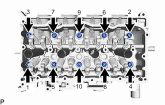
Using a 10 mm bi-hexagon socket wrench, uniformly loosen the 10 cylinder head set bolts in the order shown in the illustration. Remove the 10 cylinder head set bolts and 10 cylinder head set plate washers.
Note
-
Be careful not to drop cylinder head plate washers into the cylinder head sub-assembly.
-
Warpage or cracking of the cylinder head sub-assembly may result from removing bolts in the incorrect order.
Tech Tips
Arrange the removed parts in such a way that they can be reinstalled to their original locations.
-
-
Remove the cylinder head sub-assembly.
-
-
REMOVE CYLINDER HEAD GASKET
-
Remove the cylinder head gasket from the cylinder block sub-assembly.
-
-
INSPECT CYLINDER HEAD SET BOLT
-
INSPECT CYLINDER HEAD SUB-ASSEMBLY