CAMSHAFT OIL CONTROL VALVE(for Bank 1) REMOVAL
CAUTION / NOTICE / HINT
The necessary procedures (adjustment, calibration, initialization or registration) that must be performed after parts are removed and installed, or replaced during water inlet with camshaft timing gear bolt removal/installation are shown below.
| Replaced Part or Performed Procedure | Necessary Procedure | Effect/Inoperative Function when Necessary Procedure not Performed | Link | |
|---|---|---|---|---|
| Battery terminal is disconnected/reconnected | Memorize steering angle neutral point | LKA /LDA system | ||
| Intelligent clearance sonar system*1 | ||||
| Pre-crash safety system | ||||
| Lighting system (EXT)
|
||||
| Adaptive high beam system | ||||
| Drive the vehicle until stop and start control is permitted (approximately 15 to 60 minutes) | Stop and start system | |||
| Memorize steering angle neutral point | Parking assist monitor system (w/ Parallel parking assist function) | |||
| Parking assist monitor system (w/o Parallel parking assist function) | ||||
| Panoramic view monitor system | ||||
| Initialize back door lock | Power door lock control system | |||
| Reset back door close position | Power back door system | |||
| Replacement of ECM | Perform Vehicle Identification Number (VIN) or frame number registration |
|
Click here w/ Canister Pump Module Click here w/o Canister Pump Module |
|
| ECU Communication ID Registration (Immobiliser system) | Engine start function | See Service Bulletin for the registration method. | ||
| Perform code registration (Immobiliser system) |
|
|||
| Replacement of ECM (If possible, read the transaxle compensation code from the previous ECM) |
Possible to read transaxle compensation code | Perform the following procedures in the order shown:
|
|
Click here for Initialization (U881E) Click here for Registration (U881E) Click here for Initialization (U881F) Click here for Registration (U881F) |
| Impossible to read transaxle compensation code | Perform the following procedures in the order shown:
|
|||
| Gas leak from exhaust system is repaired | Inspection After Repair |
|
Click here w/ Canister Pump Module Click here w/o Canister Pump Module |
|
| Suspension, tires, etc. (The vehicle height changes because of suspension or tire replacement) |
|
|
||
| Rear television camera assembly optical axis (Back camera position setting) | Parking assist monitor system (w/ Parallel Parking Assist Function) | Click here for Initialization Click here for Calibration |
||
| Parking assist monitor system (w/o Parallel Parking Assist Function) | for Calibration Click here for Initialization |
|||
|
Panoramic view monitor system | Click here for Initialization Click here for Calibration |
||
| Initialize headlight ECU sub-assembly LH |
|
|||
| Front wheel alignment adjustment |
|
|
||
*1: When performing learning using the GTS.
*2: w/ TFT Meter Type
CAUTION:
-
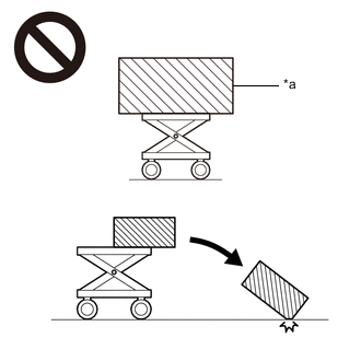
*a An Object Exceeding Weight Limit of Engine Lifter The engine assembly with transaxle is very heavy. Be sure to follow the procedure described in the repair manual, or the engine lifter may suddenly drop or the engine assembly with transaxle may fall off the engine lifter.
-
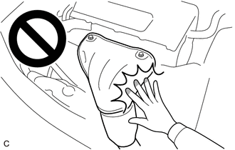
To prevent burns, do not touch the engine, exhaust manifold or other high temperature components while the engine is hot.
PROCEDURE
-
REMOVE ENGINE ASSEMBLY WITH TRANSAXLE
-
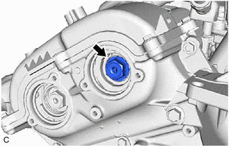
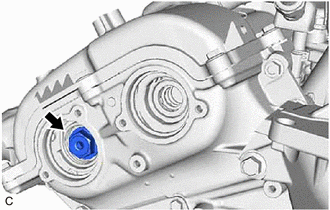
REMOVE CAMSHAFT TIMING OIL CONTROL SOLENOID ASSEMBLY (for Intake Side of Bank 1)
-
REMOVE CAMSHAFT TIMING OIL CONTROL SOLENOID ASSEMBLY (for Exhaust Side of Bank 1)
-
SET NO. 1 CYLINDER TO TDC/COMPRESSION
-
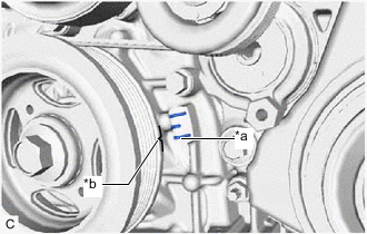
*a Timing Mark *b Timing Mark (Cutout) Turn the crankshaft pulley assembly clockwise until its timing mark (cutout) is aligned with the timing mark on the timing chain cover assembly as shown in the illustration.
-
Check that the cutout of the camshaft timing gear assembly is at the top.
-
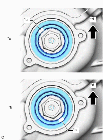
*a Correct *b Incorrect *c Cutout *d Up for intake side:
Tech Tips
If the cutout of the camshaft timing gear assembly (for intake side) is not at the top, turn the crankshaft 360° clockwise and align the timing mark (cutout) of the crankshaft pulley with the timing mark on the timing chain cover assembly again.
-
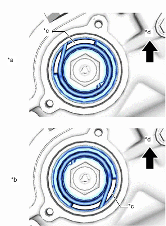
*a Correct *b Incorrect *c Cutout *d Up for exhaust side:
Tech Tips
If the cutout of the camshaft timing gear assembly (for exhaust side) is not at the top, turn the crankshaft 360° clockwise and align the timing mark (cutout) of the crankshaft pulley with the timing mark on the timing chain cover assembly again.
-
-
-
REMOVE CAMSHAFT TIMING GEAR BOLT (for Intake Side of Bank 1)
-
While holding the crankshaft pulley, remove the camshaft timing gear bolt.
Note
-
If the camshaft timing gear bolt has been struck or dropped, replace it.
-
Do not turn the crankshaft pulley after removing the camshaft timing gear bolt.
-
-
-
REMOVE CAMSHAFT TIMING GEAR BOLT (for Exhaust Side of Bank 1)
-
While holding the crankshaft pulley, remove the camshaft timing gear bolt.
Note
-
If the camshaft timing gear bolt has been struck or dropped, replace it.
-
Do not turn the crankshaft pulley after removing the camshaft timing gear bolt.
-
-