REAR SUSPENSION MEMBER(for AWD) REMOVAL

CAUTION / NOTICE / HINT
The necessary procedures (adjustment, calibration, initialization, or registration) that must be performed after parts are removed and installed, or replaced during rear suspension member sub-assembly removal/installation are shown below.
| Replaced Part or Performed Procedure | Necessary Procedure | Effect/Inoperative Function when Necessary Procedure not Performed | Link |
|---|---|---|---|
| Rear wheel alignment adjustment |
|
|
|
| Suspension, tires, etc. (The vehicle height changes because of suspension or tire replacement) |
|
|
|
| Rear television camera assembly optical axis (Back camera position setting) | Parking assist monitor system (w/ Parallel Parking Assist Function) | for Initialization: Click here for Calibration: Click here |
|
| Rear television camera assembly optical axis (Back camera position setting) | Parking assist monitor system (w/o Parallel Parking Assist Function) | for Initialization: Click here for Calibration: Click here |
|
|
Panoramic view monitor system | for Initialization: Click here for Calibration: Click here |
|
| Initialize headlight ECU sub-assembly LH |
|
||
| Rear height control sensor sub-assembly RH | Initialize headlight ECU sub-assembly LH |
|
|
| Gas leak from exhaust system is repaired | Inspection After Repair |
|
for 8AR-FTS: Click here for 2GR-FKS w/ Canister Pump Module: Click here for 2GR-FKS w/o Canister Pump Module: Click here |
| Disconnect cable from negative battery terminal | Memorize steering angle neutral point | LKA/LDA System | |
| Intelligent clearance sonar system*2 | |||
| Pre-crash safety system | |||
| Lighting system (EXT)
|
|||
| Adaptive high beam system | |||
| Drive the vehicle until stop and start control is permitted (approximately 15 to 60 minutes) | Stop and start system | ||
| Memorize steering angle neutral point | Parking Assist Monitor System (w/ Parallel Parking Assist Function) | ||
| Parking Assist Monitor System (w/o Parallel Parking Assist Function) | |||
| Panoramic view monitor system | |||
| Initialize back door lock | Power door lock control system | ||
| Reset back door close position | Power back door system |
*2: When performing learning using the GTS.
Click here Click here
PROCEDURE
-
REMOVE REAR WHEEL
-
REMOVE TAIL EXHAUST PIPE ASSEMBLY
for 8AR-FTS: Click here
for 2GR-FKS: Click here
-
REMOVE PROPELLER WITH CENTER BEARING SHAFT ASSEMBLY
-
REMOVE REAR SUSPENSION ARM COVER LH
-
REMOVE REAR SUSPENSION ARM COVER RH
Tech Tips
Perform the same procedure as for the LH side.
-
REMOVE REAR AXLE SHAFT NUT LH
-
REMOVE REAR AXLE SHAFT NUT RH
Tech Tips
Perform the same procedure as for the LH side.
-
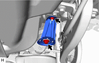
SEPARATE REAR FLEXIBLE HOSE LH
-
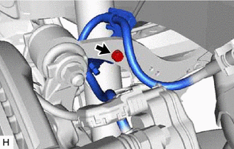
Remove the bolt and separate the rear flexible hose LH from the rear upper control arm assembly LH.
-
-
SEPARATE REAR FLEXIBLE HOSE RH
Tech Tips
Perform the same procedure as for the LH side.
-
REMOVE REAR HEIGHT CONTROL SENSOR SUB-ASSEMBLY RH
-
SEPARATE NO. 2 PARKING BRAKE WIRE ASSEMBLY
-
SEPARATE NO. 1 PARKING BRAKE WIRE ASSEMBLY
Tech Tips
Perform the same procedure as for the LH side.
-
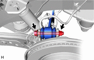
SEPARATE REAR SPEED SENSOR LH
-
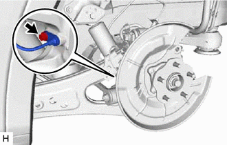
Remove the bolt and separate the rear speed sensor LH from the rear axle carrier sub-assembly LH.
Note
-
Prevent foreign matter from contacting the sensor tip.
-
Clean the speed sensor installation hole and the contact surfaces every time the speed sensor is removed.
-
Be careful not to damage the rear speed sensor LH.
-
-
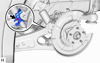
Remove the bolt and separate the rear speed sensor LH from the rear trailing arm assembly LH.
-
-
SEPARATE REAR SPEED SENSOR RH
Tech Tips
Perform the same procedure as for the LH side.
-
REMOVE REAR SPEED SENSOR LH (w/o AVS)
-
Disconnect the connector.
-
Remove the 2 bolts, nut and rear speed sensor LH.
-
-
REMOVE REAR SPEED SENSOR RH (w/o AVS)
-
Disconnect the connector and disengage the 2 clamps.
-
Remove the 2 bolts, nut and rear speed sensor RH.
-
-
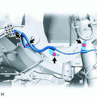
REMOVE REAR NO. 2 SKID CONTROL SENSOR WIRE LH (w/ AVS)
-
Disconnect the 3 connectors.
-
Remove the 2 bolts, 4 nuts and rear No. 2 skid control sensor wire LH.
-
-
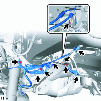
REMOVE REAR NO. 2 SKID CONTROL SENSOR WIRE RH (w/ AVS)
-
Disconnect the 3 connectors and disengage the 3 clamps.
-
Remove the 2 bolts, 4 nuts and rear No. 2 skid control sensor wire RH.
-
-
REMOVE REAR STABILIZER LINK ASSEMBLY LH
-
REMOVE REAR STABILIZER LINK ASSEMBLY RH
Tech Tips
Perform the same procedure as for the LH side.
-
REMOVE REAR STABILIZER BAR
w/o Rear No. 2 Seat: Click here
w/ Rear No. 2 Seat: Click here
-
REMOVE REAR COIL SPRING LH
-
REMOVE REAR COIL SPRING RH
Tech Tips
Perform the same procedure as for the LH side.
-
REMOVE REAR LOWER COIL SPRING INSULATOR LH
-
REMOVE REAR LOWER COIL SPRING INSULATOR RH
Tech Tips
Perform the same procedure as for the LH side.
-
REMOVE REAR NO. 2 SUSPENSION ARM ASSEMBLY LH
-
REMOVE REAR NO. 2 SUSPENSION ARM ASSEMBLY RH
Tech Tips
Perform the same procedure as for the LH side.
-
REMOVE REAR NO. 1 SUSPENSION ARM ASSEMBLY LH
-
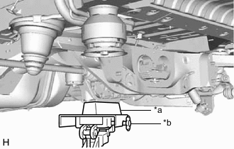
*a Wooden Block *b Transmission Jack Using a transmission jack and a wooden block, support the rear differential carrier assembly.
-
Remove the bolt, nut and rear lower suspension member stopper LH.
-
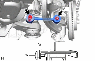
*a Wooden Block *b Transmission Jack Using a transmission jack and a wooden block, support the rear axle carrier sub-assembly LH.
-
Remove the nut (A) and spacer.
-
Remove the bolt (B), nut and rear No. 1 suspension arm assembly LH from the rear axle carrier sub-assembly LH and rear suspension member sub-assembly.
Note
Because the nut has its own stopper, do not turn the nut. Loosen the bolt with the nut secured.
-
Temporarily install the rear lower suspension member stopper LH with the bolt and nut.
-
-
REMOVE REAR NO. 1 SUSPENSION ARM ASSEMBLY RH
Tech Tips
Perform the same procedure as for the LH side.
-
SEPARATE REAR UPPER CONTROL ARM ASSEMBLY LH
-
Remove the bolt and nut and separate the rear upper control arm assembly LH from the rear axle carrier sub-assembly LH.
Note
Because the nut has its own stopper, do not turn the nut. Loosen the bolt with the nut secured.
-
-
SEPARATE REAR UPPER CONTROL ARM ASSEMBLY RH
Tech Tips
Use the same procedure as for the LH side.
-
DRAIN DIFFERENTIAL OIL
-
REMOVE REAR DRIVE SHAFT ASSEMBLY LH
-
REMOVE REAR DRIVE SHAFT ASSEMBLY RH
Tech Tips
Use the same procedure as for the LH side.
-
REMOVE REAR DRIVE SHAFT SNAP RING (for LH Side)
-
REMOVE REAR DRIVE SHAFT SNAP RING (for RH Side)
Tech Tips
Use the same procedure as for the LH side.
-
REMOVE REAR DIFFERENTIAL CARRIER ASSEMBLY
-
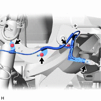
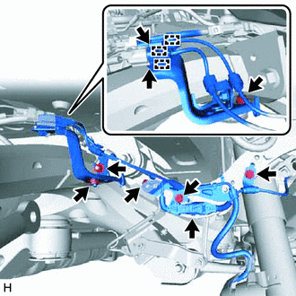
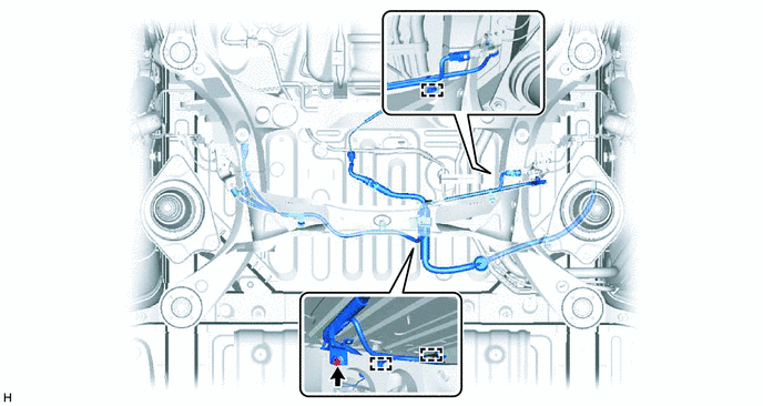
SEPARATE NO. 3 FLOOR WIRE
-
Remove the bolt and disengage the 3 clamps to separate the No. 3 floor wire from rear suspension member sub-assembly.
-
-
REMOVE REAR SUSPENSION MEMBER SUB-ASSEMBLY
-
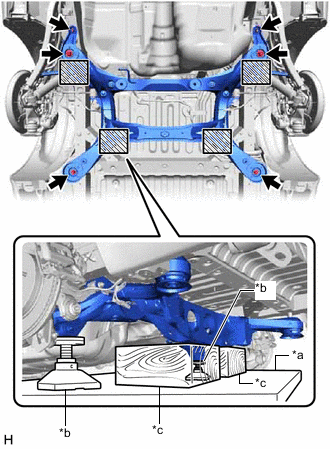
*a Engine Lifter *b Attachment *c Wooden Block 
Attachment and Wooden Block Placement Location Using an engine lifter, 2 attachments and 2 wooden blocks or equivalent tools, support the rear suspension member sub-assembly as shown in the illustration.
CAUTION:
-
The rear suspension member sub-assembly is a very heavy component. Make sure that it is supported securely.
-
If the rear suspension member sub-assembly is not securely supported, it may drop, resulting in serious injury.
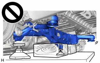
Note
Use attachments and wooden blocks to keep the rear suspension member sub-assembly level.
-
-
Remove the 4 bolts, 2 nuts, 2 rear lower suspension braces, rear lower suspension member stopper LH and rear lower suspension member stopper RH.
-
Slowly lower the rear suspension member sub-assembly.
Note
When lowering the rear suspension member sub-assembly, be careful not to damage the vehicle body or other components installed to the vehicle.
-
-
REMOVE REAR SUSPENSION MEMBER UPPER STOPPER
-
Remove the 2 rear suspension member upper stoppers from the rear suspension member sub-assembly.
-
-
REMOVE REAR SUSPENSION MEMBER REAR UPPER STOPPER
-
Remove the 2 rear suspension member rear upper stoppers from the rear suspension member sub-assembly.
-
-
REMOVE REAR UPPER CONTROL ARM ASSEMBLY LH
-
REMOVE REAR UPPER CONTROL ARM ASSEMBLY RH
Tech Tips
Perform the same procedure as for the LH side.
-
REMOVE REAR NO. 2 DIFFERENTIAL MOUNT CUSHION
-
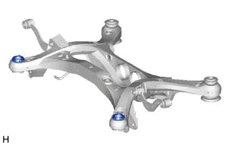
REMOVE REAR SUSPENSION MEMBER FRONT BODY MOUNTING CUSHION (for LH Side)
-
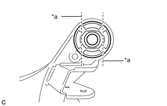
*a Bend Portion Using a chisel and hammer, bend the 2 portions of the rear suspension member front body mounting cushion rib.
Note
Make sure to bend the 2 portions of the cushion rib until the claws of SST can fit securely.
-
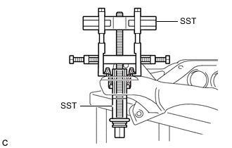
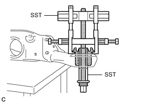
Install SST as shown in the illustration.
- SST
- 09830-10010 ( 09830-01010, 09830-01040, 09830-01050 )
- 09950-40011 ( 09951-04020, 09952-04010, 09954-04010, 09955-04051, 09958-04011 )
Note
Apply grease to the threads and tip of the SST center bolt before use.
-
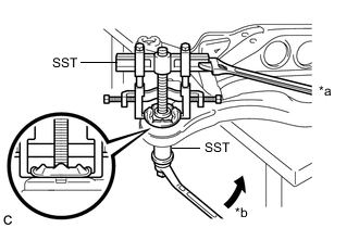
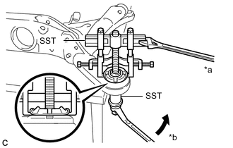
*a Hold *b Turn Using SST, remove the rear suspension member front body mounting cushion while applying grease into the clearance between the rear suspension member front body mounting cushion and the rear suspension member sub-assembly.
- SST
- 09830-10010 ( 09830-01010, 09830-01040, 09830-01050 )
- 09950-40011 ( 09951-04020, 09952-04010, 09954-04010, 09955-04051, 09958-04011 )
Note
-
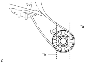
Set the claws of SST onto the rear suspension member sub-assembly securely as shown in the illustration.
-
Be careful as the rear suspension member front body mounting cushion may fly out.
-
The rear suspension member front body mounting cushion cannot be reused.
-
Remove SST and the rear suspension member front body mounting cushion (LH Side) from the rear suspension member sub-assembly.
-
-
REMOVE REAR SUSPENSION MEMBER FRONT BODY MOUNTING CUSHION (for RH Side)
Tech Tips
Perform the same procedure as for the LH side.
-
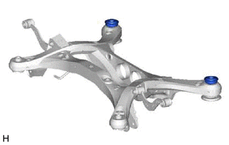
REMOVE REAR SUSPENSION MEMBER REAR BODY MOUNT CUSHION LH
-
*a Bend Portion Using a chisel and hammer, bend the 2 portions of the rear suspension member rear body mount cushion LH rib.
Note
Make sure to bend the 2 portions of the cushion rib until the claws of SST can fit securely.
-
Install SST as shown in the illustration.
- SST
- 09830-10010 ( 09830-01010, 09830-01040, 09830-01050 )
- 09950-40011 ( 09951-04020, 09952-04010, 09954-04010, 09955-04051, 09958-04011 )
Note
Apply grease to the threads and tip of the SST center bolt before use.
-
*a Hold *b Turn Using SST, remove the rear suspension member rear body mount cushion LH while applying grease into the clearance between the rear suspension member rear body mount cushion LH and the rear suspension member sub-assembly.
- SST
- 09830-10010 ( 09830-01010, 09830-01040, 09830-01050 )
- 09950-40011 ( 09951-04020, 09952-04010, 09954-04010, 09955-04051, 09958-04011 )
Note
-
Set the claws of SST onto the rear suspension member sub-assembly securely as shown in the illustration.
-
Be careful as the rear suspension member rear body mount cushion LH may fly out.
-
The rear suspension member rear body mount cushion LH cannot be reused.
-
Remove SST and the rear suspension member rear body mount cushion LH from the rear suspension member sub-assembly.
-
-
REMOVE REAR SUSPENSION MEMBER REAR BODY MOUNT CUSHION RH
Tech Tips
Perform the same procedure as for the LH side.
-
REMOVE HOLE PLUG
-
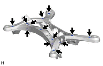
Remove the 13 hole plugs from the rear suspension member sub-assembly as shown in the illustration.
-