REAR UPPER ARM REMOVAL
CAUTION / NOTICE / HINT
The necessary procedures (adjustment, calibration, initialization, or registration) that must be performed after parts are removed and installed, or replaced during rear upper control arm assembly removal/installation are shown below.
| Replaced Part or Performed Procedure | Necessary Procedure | Effect/Inoperative Function when Necessary Procedure not Performed | Link |
|---|---|---|---|
| Rear wheel alignment adjustment |
|
|
|
| Suspension, tires, etc. (The vehicle height changes because of suspension or tire replacement) |
|
|
|
| Rear television camera assembly optical axis (Back camera position setting) | Parking assist monitor system (w/ Parallel Parking Assist Function) | for Initialization: Click here for Calibration: Click here |
|
| Rear television camera assembly optical axis (Back camera position setting) | Parking assist monitor system (w/o Parallel Parking Assist Function) | for Initialization: Click here for Calibration: Click here |
|
|
Panoramic view monitor system | for Initialization: Click here for Calibration: Click here |
|
| Initialize headlight ECU sub-assembly LH |
|
||
| Rear height control sensor sub-assembly RH | Initialize headlight ECU sub-assembly LH |
|
|
| Gas leak from exhaust system is repaired | Inspection After Repair |
|
for 8AR-FTS: Click here for 2GR-FKS w/ Canister Pump Module: Click here for 2GR-FKS w/o Canister Pump Module: Click here |
| Disconnect cable from negative battery terminal | Memorize steering angle neutral point | LKA/LDA System | |
| Intelligent clearance sonar system*2 | |||
| Pre-crash safety system | |||
| Lighting system (EXT)
|
|||
| Adaptive high beam system | |||
| Drive the vehicle until stop and start control is permitted (approximately 15 to 60 minutes) | Stop and start system | ||
| Memorize steering angle neutral point | Parking Assist Monitor System (w/ Parallel Parking Assist Function) | ||
| Parking Assist Monitor System (w/o Parallel Parking Assist Function) | |||
| Panoramic view monitor system | |||
| Initialize back door lock | Power door lock control system | ||
| Reset back door close position | Power back door system |
*2: When performing learning using the GTS.
Click here Click here
PROCEDURE
-
REMOVE REAR SUSPENSION MEMBER SUB-ASSEMBLY
-
for 2WD: Click here
-
for AWD: Click here
-
-
REMOVE REAR UPPER CONTROL ARM ASSEMBLY LH
-
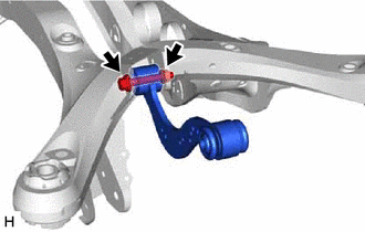
Remove the bolt, nut and rear upper control arm assembly LH from the rear suspension member sub-assembly.
Note
Because the nut has its own stopper, do not turn the nut. Loosen the bolt with the nut secured.
-
-
REMOVE REAR UPPER CONTROL ARM ASSEMBLY RH
Tech Tips
Perform the same procedure as for the LH side.