INSTRUMENT PANEL SAFETY PAD REMOVAL
PROCEDURE
-
PRECAUTION
Note
After turning the engine switch off, waiting time may be required before disconnecting the cable from the negative (-) battery terminal. Therefore, make sure to read the disconnecting the cable from the negative (-) battery terminal notices before proceeding with work Click here.
-
DISCONNECT CABLE FROM NEGATIVE BATTERY TERMINAL
-
for Power Tilt and Power Telescopic Steering Column:
-
Disable the auto away/return function by changing the customize parameter Click here.
Note
Record the current customize parameter setting (whether the auto away/return function is enabled or disabled) in order to restore the current setting after finishing this operation.
Tech Tips
Performing the above operation disables the auto away/return function when the engine switch is turned off.
-
Turn the engine switch on (IG). Operate the tilt and telescopic switch to fully extend and lower the steering column assembly.
-
Turn the engine switch off and disconnect the cable from the negative (-) battery terminal.
CAUTION:
Wait at least 90 seconds after disconnecting the cable from the negative (-) battery terminal to disable the SRS system.
Note
When disconnecting the cable, some systems need to be initialized after the cable is reconnected Click here.
-
-
-
REMOVE HORN BUTTON ASSEMBLY
-
REMOVE STEERING WHEEL ASSEMBLY
-
REMOVE LOWER STEERING COLUMN COVER (for Manual Tilt and Manual Telescopic Steering Column)
-
REMOVE LOWER STEERING COLUMN COVER (for Power Tilt and Power Telescopic Steering Column)
-
REMOVE UPPER STEERING COLUMN COVER
-
REMOVE TURN SIGNAL SWITCH ASSEMBLY WITH SPIRAL CABLE SUB-ASSEMBLY
-
REMOVE INSTRUMENT CLUSTER FINISH PANEL SUB-ASSEMBLY
-
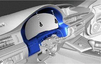
Remove the 2 screws <E>.
-
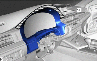
Text in Illustration *a Protective Tape Apply protective tape to the area shown in the illustration.
-
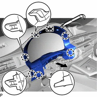
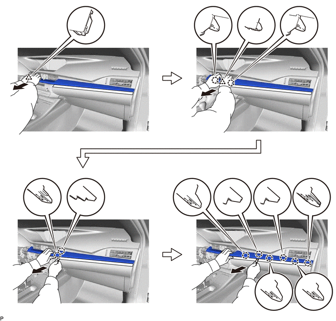
Using a moulding remover, disengage the 5 claws and 2 guides as shown in the illustration.
-
Disconnect the connector to remove the instrument cluster finish panel sub-assembly.
-
-
REMOVE CENTER INSTRUMENT CLUSTER FINISH PANEL GARNISH
-
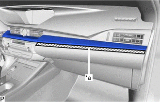
Text in Illustration *a Protective Tape Apply protective tape to the area shown in the illustration.
-
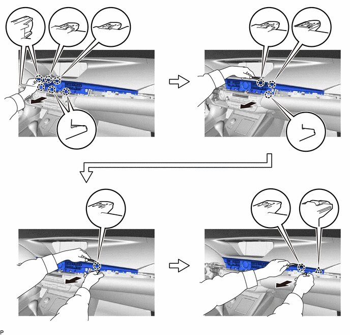
Using a moulding remover, disengage the 10 claws and 2 clips as shown in the illustration.
-
Disconnect the connector to remove the center instrument cluster finish panel garnish.
-
-
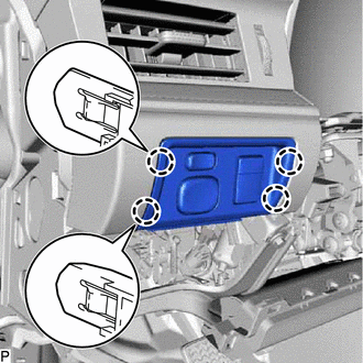
REMOVE NO. 2 INSTRUMENT PANEL REGISTER ASSEMBLY
-
Using a moulding remover, disengage the 11 claws and clip as shown in the illustration.
-
Disconnect the connector to remove the No. 2 instrument panel register assembly.
-
-
REMOVE LOWER CENTER INSTRUMENT PANEL FINISH PANEL
-
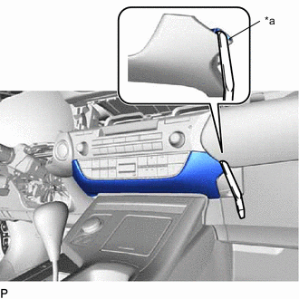
Text in Illustration *a Lower Center Instrument Panel Finish Panel Hole Insert a moulding remover as shown in the illustration.
-
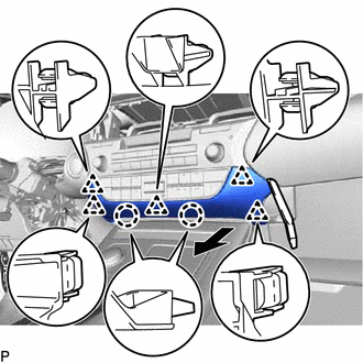
Using a moulding remover, disengage the 2 claws and 5 clips and remove the lower center instrument panel finish panel as shown in the illustration.
-
-
REMOVE RADIO RECEIVER ASSEMBLY WITH BRACKET
-
REMOVE FRONT DOOR SCUFF PLATE LH
-
REMOVE COWL SIDE TRIM BOARD LH
-
REMOVE FRONT DOOR OPENING TRIM COVER LH
-
REMOVE INSTRUMENT SIDE PANEL LH
-
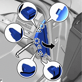
Using a moulding remover, disengage the 2 claws and 4 clips as shown in the illustration.
-
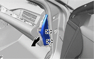
Disengage the 2 guides and remove the instrument side panel LH as shown in the illustration.
-
-
DISCONNECT HOOD LOCK CONTROL LEVER SUB-ASSEMBLY
-
Disengage the claw and 2 guides to disconnect the hood lock control lever sub-assembly.
-
-
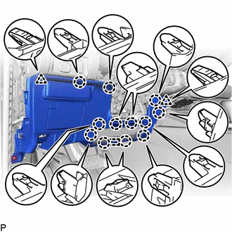
REMOVE LOWER NO. 1 INSTRUMENT PANEL FINISH PANEL
-
for LHD:
-
Remove the 2 bolts <B>.
-
Disengage the 12 claws, 2 clips and guide.
-
Disconnect each connector and disengage each clamp to remove the lower No. 1 instrument panel finish panel.
-
-
for RHD:
-
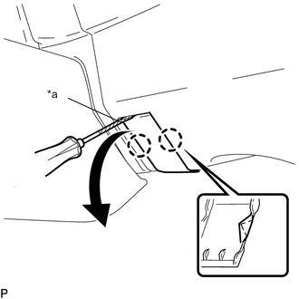
Text in Illustration *a Protective Tape Using a screwdriver, disengage the 2 claws and open the cover.
Tech Tips
Tape the screwdriver tip before use.
-
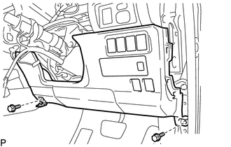
Remove the 2 bolts <B>.
-
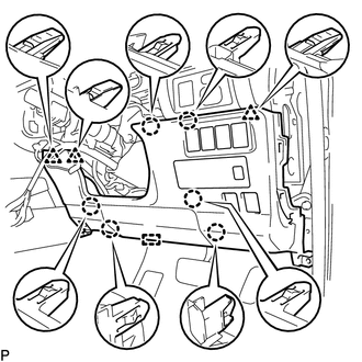
Disengage the 6 claws, 3 clips and guide.
-
Disconnect each connector and disengage each clamp to remove the lower No. 1 instrument panel finish panel.
-
-
-
REMOVE COMBINATION METER ASSEMBLY
-
REMOVE NO. 1 SWITCH HOLE BASE
-
Disengage the 4 claws.
-
Disconnect each connector to remove the No. 1 switch hole base.
-
-
REMOVE NO. 1 INSTRUMENT PANEL REGISTER ASSEMBLY
-
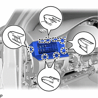
Disengage the 6 claws and 2 guides to remove the No. 1 instrument panel register assembly.
-
-
REMOVE SWITCH BASE
-
for LHD:
-
Disengage the 3 claws.
-
Disconnect the connector to remove the switch base.
-
-
for RHD:
-
Disengage the 4 claws.
-
Disconnect the connector to remove the switch base.
-
-
-
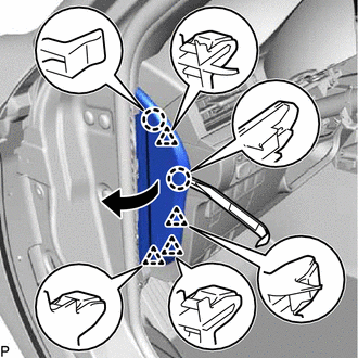
REMOVE CENTER INSTRUMENT CLUSTER FINISH PANEL SUB-ASSEMBLY
-
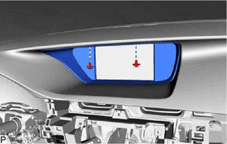
Remove the 2 clips.
-
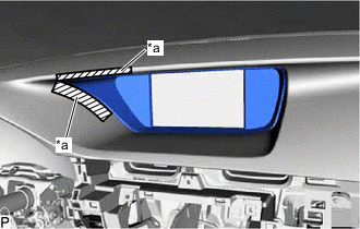
Text in Illustration *a Protective Tape Apply protective tape to the areas shown in the illustration.
-
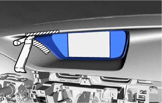
Insert a moulding remover as shown in the illustration.
-
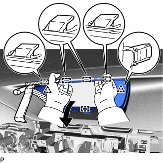
Pull the center instrument cluster finish panel sub-assembly in the direction indicated by the arrow shown in the illustration to disengage the 2 clips and 5 guides, and remove the center instrument cluster finish panel sub-assembly.
-
-
REMOVE MULTI-DISPLAY ASSEMBLY
-
REMOVE REAR CONSOLE BOX ASSEMBLY
-
REMOVE FRONT DOOR SCUFF PLATE RH
Tech Tips
Use the same procedure as for the LH side Click here.
-
REMOVE COWL SIDE TRIM BOARD RH
Tech Tips
Use the same procedure as for the LH side Click here.
-
REMOVE FRONT DOOR OPENING TRIM COVER RH
Tech Tips
Use the same procedure as for the LH side Click here.
-
REMOVE INSTRUMENT SIDE PANEL RH
-
Using a moulding remover, disengage the 2 claws and 4 clips as shown in the illustration.
-
Disengage the 2 guides and remove the instrument side panel RH as shown in the illustration.
-
-
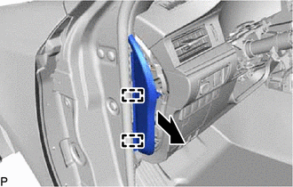
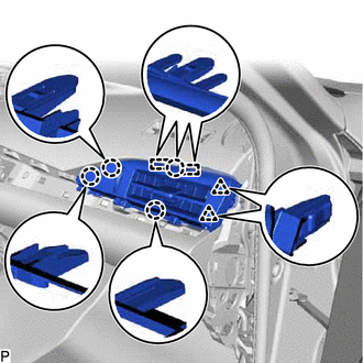
REMOVE NO. 2 INSTRUMENT PANEL UNDER COVER SUB-ASSEMBLY
-
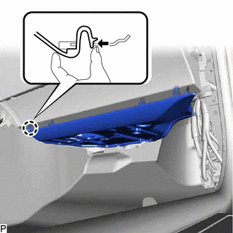
Disengage the claw as shown in the illustration.
-
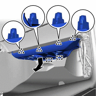
Disengage the 4 clips and 2 guides as shown in the illustration.
-
Disconnect the connector to remove the No. 2 instrument panel under cover sub-assembly.
-
-
REMOVE LOWER NO. 2 INSTRUMENT PANEL AIRBAG ASSEMBLY
-
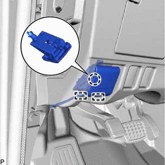
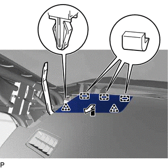
REMOVE INSTRUMENT PANEL BOX DOOR COVER
-
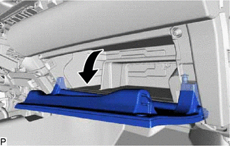
Open the lower instrument panel sub-assembly door as shown in the illustration.
-
Using a moulding remover, disengage the 4 claws and remove the instrument panel box door cover as shown in the illustration.
-
-
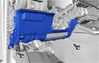
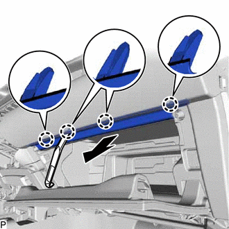
REMOVE LOWER INSTRUMENT PANEL SUB-ASSEMBLY
-
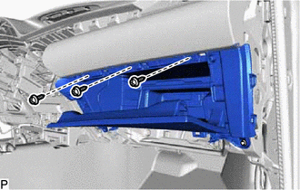
Remove the 3 screws <E>.
-
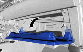
Close the lower instrument panel sub-assembly door as shown in the illustration.
-
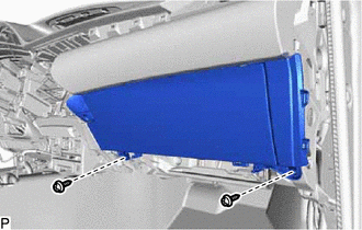
Remove the 2 screws <E>.
-
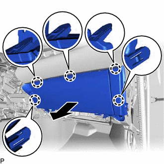
Disengage the 5 claws as shown in the illustration.
-
Disconnect each connector and remove the lower instrument panel sub-assembly.
-
-
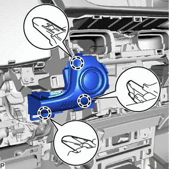
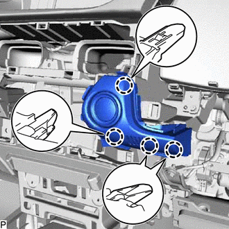
REMOVE NO. 3 INSTRUMENT PANEL REGISTER ASSEMBLY
-
Disengage the 4 claws, 2 clips and 2 guides and remove the No. 3 instrument panel register assembly.
-
-
REMOVE FRONT PILLAR GARNISH LH
-
REMOVE NO. 1 INSTRUMENT PANEL SPEAKER PANEL SUB-ASSEMBLY
-
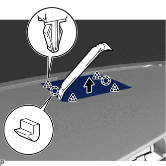
Using a moulding remover, disengage the 2 clips as shown in the illustration.
-
Disengage the 3 guides to remove the No. 1 instrument panel speaker panel sub-assembly as shown in the illustration.
-
-
REMOVE FRONT NO. 2 SPEAKER ASSEMBLY (for LH Side)
-
REMOVE NO. 1 SPEAKER OPENING COVER ASSEMBLY
-
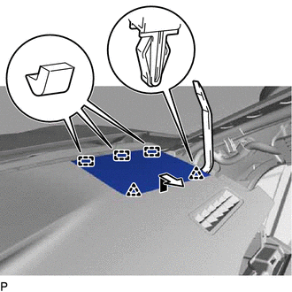
Using a moulding remover, disengage the 2 claws and 4 clips and remove the No. 1 speaker opening cover assembly as shown in the illustration.
-
-
REMOVE FRONT NO. 3 SPEAKER ASSEMBLY
-
REMOVE FRONT PILLAR GARNISH RH
Tech Tips
Use the same procedure as for the LH side Click here.
-
REMOVE NO. 2 INSTRUMENT PANEL SPEAKER PANEL SUB-ASSEMBLY
-
Using a moulding remover, disengage the 2 clips as shown in the illustration.
-
Disengage the 3 guides to remove the No. 2 instrument panel speaker panel sub-assembly as shown in the illustration.
-
-
REMOVE FRONT NO. 2 SPEAKER ASSEMBLY (for RH Side)
Tech Tips
Use the same procedure as for the LH side Click here.
-
REMOVE NO. 1 ION GENERATOR SUB-ASSEMBLY (w/ Ion Generator)
-
REMOVE INSTRUMENT PANEL FINISH PANEL SUB-ASSEMBLY
-
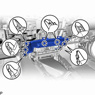
Disengage the 8 claws to remove the instrument panel finish panel sub-assembly.
-
-
DISCONNECT NO. 2 INSTRUMENT PANEL WIRE
-
REMOVE INSTRUMENT PANEL SAFETY PAD ASSEMBLY
-
for LHD:
-
Disconnect each connector.
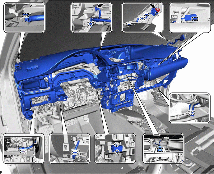
Text in Illustration *1 Cooler (Room Temp. Sensor) Thermistor - - -
Disengage the claw and each clamp.
-
Disengage the 2 claws to disconnect the cooler (room temp. sensor) thermistor.
-
-
for RHD:
-
Disconnect each connector.
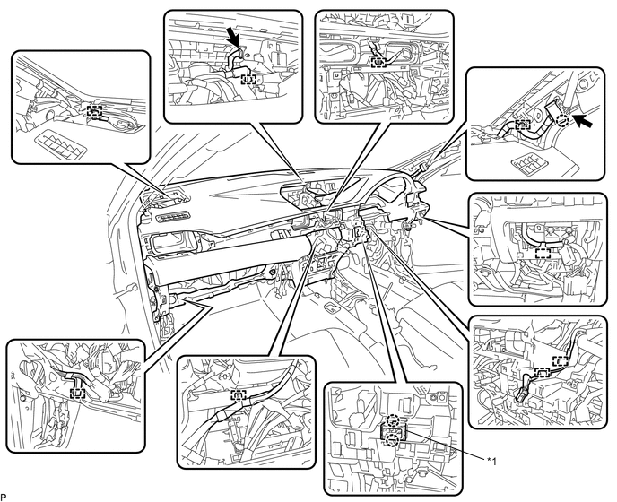
Text in Illustration *1 Cooler (Room Temp. Sensor) Thermistor - - -
Disengage the claw and each clamp.
-
Disengage the 2 claws to disconnect the cooler (room temp. sensor) thermistor.
-
-
Remove the 2 bolts <A>.
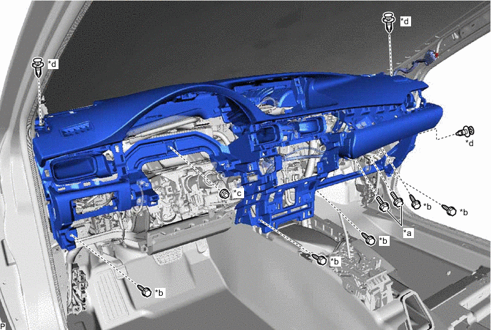
Text in Illustration *a Bolt <A> *b Bolt <C> *c Nut <F> *d Clip -
Remove the 5 bolts <C> and nut <F>.
-
Remove the 3 clips.
-
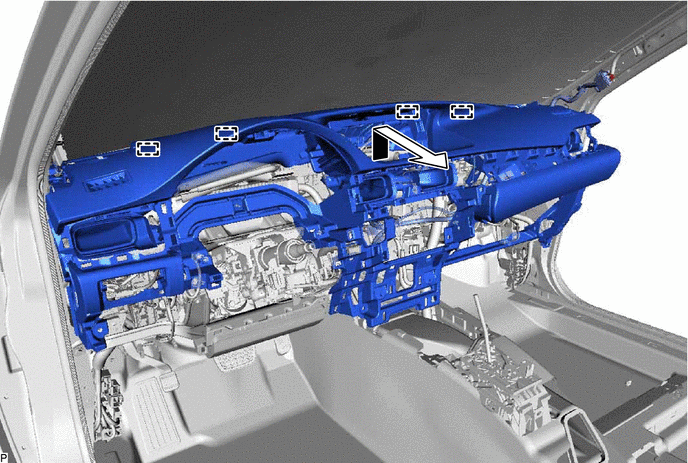
Disengage the 4 guides and remove the instrument panel safety pad assembly as shown in the illustration.
Note
-
Do not damage the instrument panel safety pad assembly.
-
Do not allow the wire harnesses to interfere with the surrounding parts.
-
-