FUEL INJECTOR(for Direct Injection) REMOVAL

CAUTION / NOTICE / HINT
The necessary procedures (adjustment, calibration, initialization or registration) that must be performed after parts are removed and installed, or replaced during fuel injector assembly (for Direct Injection) removal/installation are shown below.
| Replaced Part or Performed Procedure | Necessary Procedure | Effect/Inoperative Function when Necessary Procedure not Performed | Link |
|---|---|---|---|
| Disconnect cable from negative battery terminal | Drive the vehicle until stop and start control is permitted (approximately 5 to 60 minutes) | Stop and start system | |
| Memorize steering angle neutral point | LKA/LDA system | ||
| Parking support brake system* | |||
| Pre-collision system | |||
| Adaptive high beam system | |||
Lighting system (EXT) |
|||
| Variable gear ratio steering system | |||
| Parking assist monitor system | |||
| Panoramic view monitor system | |||
| Initialize rear door sunshade system | Rear door sunshade system | ||
| Initialize power trunk lid system | Power trunk lid system | ||
|
Inspection After Repair |
|
Click here Click here
CAUTION:
-
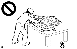
Never perform work on fuel system components near any possible ignition sources.
-
Vaporized fuel could ignite, resulting in a serious accident.
-
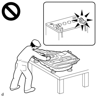
Do not perform work on fuel system components without first disconnecting the cable from the negative (-) battery terminal.
-
Sparks could cause vaporized fuel to ignite, resulting in a serious accident.
PROCEDURE
-
PRECAUTION
Note
After turning the engine switch off, waiting time may be required before disconnecting the cable from the battery terminal. Therefore, make sure to read the disconnecting the cable from the battery terminal notice before proceeding with work.
-
DISCHARGE FUEL SYSTEM PRESSURE
-
DISCONNECT CABLE FROM NEGATIVE BATTERY TERMINAL
Note
When disconnecting the cable, some systems need to be initialized after the cable is reconnected.
-
REMOVE FUEL PUMP ASSEMBLY (for High Pressure)
-
REMOVE NO. 2 FUEL PIPE SUB-ASSEMBLY
CAUTION:
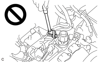
To prevent serious injury due to fuel spray from the high-pressure fuel lines, always discharge fuel system pressure before removing any fuel system components.
-
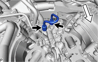

Front Using a 17 mm union nut wrench, loosen the 2 union nuts of the No. 2 fuel pipe sub-assembly.
-
Remove the No. 2 fuel pipe sub-assembly from the fuel delivery pipe with sensor assembly LH and fuel delivery pipe RH.
-
-
REMOVE FUEL DELIVERY PIPE WITH SENSOR ASSEMBLY LH
-
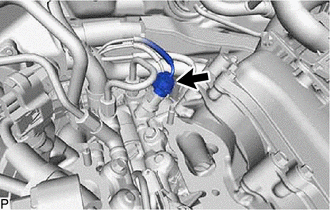
Disconnect the fuel pressure sensor connector.
Note
Do not pull the wire harness of the fuel pressure sensor excessively.
-
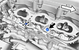
Front Remove the bolt and detach the clamp to disconnect the No. 7 engine wire from the fuel delivery pipe with sensor assembly LH.
-
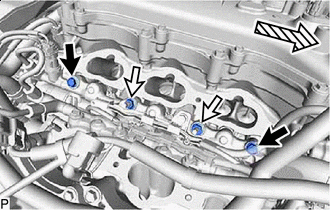

Bolt Nut 
Front Remove the 2 bolts and 2 nuts.
-
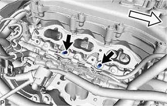
Front Using an E8 "TORX" socket wrench, remove the 2 stud bolts from the cylinder head LH.
-
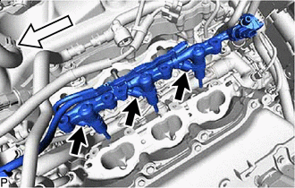
Front With the connectors still connected, disconnect the fuel delivery pipe assembly LH.
Note
-
Make sure that the fuel delivery pipe is disconnected from the fuel delivery pipe assembly LH.
-
Be extremely careful not to touch or strike the tips of the fuel injector assemblies.
-
Pull and remove the fuel delivery pipe in a straight line without tilting it.
-
-
Disconnect the 3 fuel injector connectors and remove the No. 7 engine wire.
-
-
REMOVE FUEL DELIVERY PIPE RH
-
Remove the bolt.
-
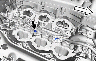
Front Remove the bolt and detach the clamp to disconnect the No. 6 engine wire from the fuel delivery pipe RH.
-

Bolt Nut Front Remove the 2 bolts and 2 nuts.
-
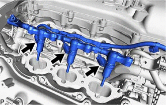
With the connectors still connected, disconnect the fuel delivery pipe RH.
Note
-
Be extremely careful not to touch or strike the tips of the fuel injector assemblies.
-
Pull and remove the fuel delivery pipe RH in a straight line without tilting it.
-
-
Disconnect the 3 injector connectors and remove the No. 6 engine wire.
-
-
REMOVE FUEL INJECTOR ASSEMBLY
-
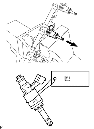
*1 No. 2 Fix the fuel delivery pipe in a vise between aluminum plates.
Note
-
Do not tighten the vise more than necessary.
-
Do not damage the fuel injector assemblies.
-
-
Remove the fuel injector assemblies from the fuel delivery pipe assembly LH and fuel delivery pipe RH.
Note
-
When removing an injector, pull the injector straight out to avoid damaging the O-ring seal surfaces of the fuel delivery pipe assembly LH and fuel delivery pipe RH.
-
After removing the fuel injector assembly, check that the O-ring, No. 1 fuel injector back-up ring and No. 3 fuel injector back-up ring are not remaining on the fuel delivery pipe. If any of the parts remain on the fuel delivery pipe, remove them.
-
Attach a label to the removed fuel injector assembly to distinguish it from other cylinders.
-
-
Remove the nozzle holder clamp from each fuel injector assembly.
-
Using needle nose pliers, remove the No. 3 fuel injector back-up ring from each fuel injector assembly.
Note
Do not damage the area that contacts the O-ring.
-
Remove the O-ring and No. 1 fuel injector back-up ring from each fuel injector assembly.
-
Remove the C-ring and injector vibration insulator from each fuel injector assembly.
-
-
REMOVE FUEL INJECTOR SEAL
-
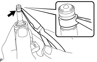
Using the tips of a pair of needle nose pliers, pinch and pull one of the fuel injector seals at several points to stretch it. Repeat this for the other fuel injector seal.
Note
-
Excessively pinching the fuel injector seal may damage the groove of the fuel injector assembly.
-
If a fuel injector assembly is dropped or the tip of the fuel injector assembly is struck, replace it with a new one.
-
-
Remove the fuel injector seal from each fuel injector assembly.
-