REAR BUMPER REMOVAL
CAUTION / NOTICE / HINT
The necessary procedures (adjustment, calibration, initialization, or registration) that must be performed after parts are removed, installed, or replaced during the rear bumper assembly removal/installation are shown below.
| Replacement Part or Procedure | Necessary Procedure | Effects / Inoperative when not Performed | Link |
|---|---|---|---|
w/ Hands Free Power Trunk Lid |
Drive the vehicle until stop and start control is permitted (approximately 5 to 60 minutes) | Stop and start system | for 8GR-FKS: for V35A-FTS: |
| Memorize steering angle neutral point | LKA/LDA system | ||
| Parking support brake system* | |||
| Pre-collision system | |||
| Adaptive high beam system | |||
Lighting system (EXT) |
|||
| Variable gear ratio steering system | |||
| Parking assist monitor system | |||
| Panoramic view monitor system | |||
| Initialize Rear Door Sunshade System | Rear door sunshade system | ||
| Initialize power trunk lid system | Power trunk lid system | ||
| Rear bumper assembly (Including removal and installation) |
|
Parking support brake system | |
w/ Parking Support Brake System |
|
|
|
| When the luggage compartment door is opened using a mechanical key | Initialize luggage closer motor assembly | The power trunk lid does not operate |
Click here Click here
Tech Tips
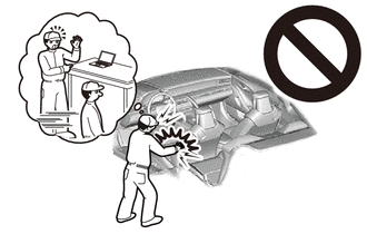
If the bumper is damaged, there is a possibility that the installation area of the blind spot monitor sensor may be deformed and the blind spot monitor system may not operate correctly, so visually inspect the blind spot monitor sensor installation area (frame, stud bolt) to make sure it is not dented or bent.
If the visual inspection finds a problem, check the installation condition of the blind spot monitor sensor, and adjust the installation position of the blind spot monitor sensor as necessary.
PROCEDURE
-
PRECAUTION (w/ Hands Free Power Trunk Lid)
Note
After turning the engine switch off, waiting time may be required before disconnecting the cable from the negative (-) battery terminal. Therefore, make sure to read the disconnecting the cable from the negative (-) battery terminal notices before proceeding with work.
-
REMOVE LUGGAGE COMPARTMENT MAT SUB-ASSEMBLY (w/ Hands Free Power Trunk Lid)
-
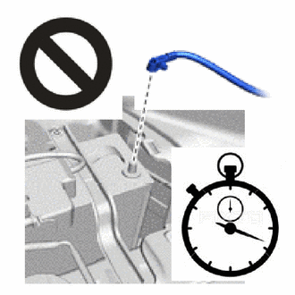
DISCONNECT CABLE FROM NEGATIVE BATTERY TERMINAL (w/ Hands Free Power Trunk Lid)
for 8GR-FKS:
for V35A-FTS:
CAUTION:
-
Wait at least 90 seconds after disconnecting the cable from the negative(-) battery terminal to disable the SRS system.
-
If the airbag deploys for any reason, it may cause a serious accident.
Note
When disconnecting the cable, some systems need to be initialized after the cable is reconnected.
-
-
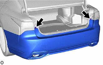
REMOVE REAR COMBINATION LIGHT COVER LH
-
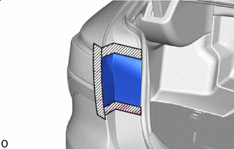

Protective Tape Put protective tape around the rear combination light cover LH.
-
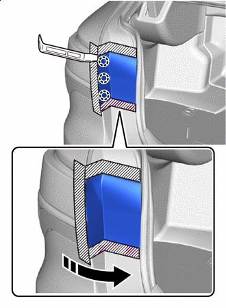

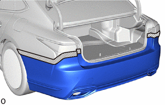
Remove in this Direction Insert moulding remover A at the position shown in the illustration and detach the claw.
-
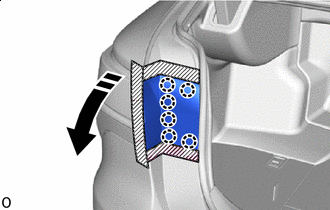
Remove in this Direction Detach the claw and remove the rear combination light cover LH.
-
-
REMOVE REAR COMBINATION LIGHT COVER RH
Tech Tips
Use the same procedure described for the LH side.
-
REMOVE REAR BUMPER ASSEMBLY
-
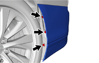
Remove the 3 clips.
Tech Tips
Use the same procedure for the RH side and LH side.
-
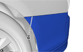
Remove the screw.
Tech Tips
Use the same procedure for the RH side and LH side.
-
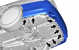
Remove the 8 clips.
-
Remove the 2 screws.
-
Protective Tape Put protective tape around the rear bumper assembly.
-
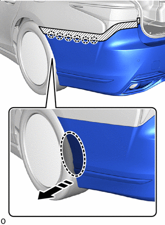

Place Hands Here Remove in this Direction Detach the claw as shown in the illustration.
Tech Tips
Use the same procedure for the RH side and LH side.
-
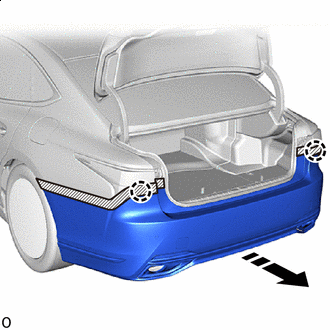
Remove in this Direction Detach the claw and remove the rear bumper assembly as shown in the illustration.
-
Disconnect the connector.
-