MANUAL TRANSMISSION ASSEMBLY REMOVAL
CAUTION / NOTICE / HINT
The necessary procedures (adjustment, calibration, initialization, or registration) that must be performed after parts are removed, installed, or replaced during the automatic transmission assembly removal/installation are shown below.
| Replacement Part or Procedure | Necessary Procedures | Effects/Inoperative when not Performed | Link |
|---|---|---|---|
| Battery terminal is disconnected/reconnected | Drive the vehicle until stop and start control is permitted (approximately 15 to 40 minutes) | Stop and start system | |
| Memorize steering angle neutral point | Pre-crash safety system |
CAUTION:
-
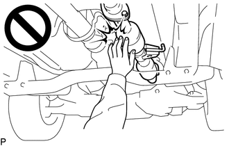
To prevent burns, do not touch the engine, exhaust pipe or other high temperature components while the engine is hot.
-
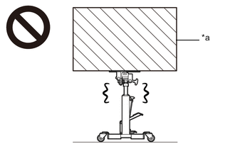
*a Object Exceeding Weight Limit of Transmission Jack The manual transmission assembly is very heavy. Be sure to follow the procedure described in the repair manual, or the transmission jack may suddenly drop or a part may fall.
PROCEDURE
-
PRECAUTION
Note
After turning the ignition switch off, waiting time may be required before disconnecting the cable from the battery terminal. Therefore, make sure to read the disconnecting the cable from the battery terminal notice before proceeding with work.
-
DISCONNECT CABLE FROM NEGATIVE BATTERY TERMINAL
Note
When disconnecting the cable, some systems need to be initialized after the cable is reconnected.
-
REMOVE SHIFT LEVER KNOB SUB-ASSEMBLY
-
Remove the shift lever knob sub-assembly from the shift lever.
-
-
REMOVE CONSOLE BOX ASSEMBLY (w/ Console Box Lid)
-
REMOVE FRONT CONSOLE BOX (w/o Console Box Lid)
-
REMOVE SHIFT LEVER BOOT ASSEMBLY
-
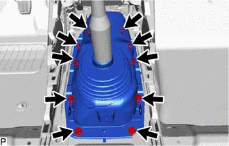
Remove the 6 screws, 4 clips and shift lever boot assembly.
-
-
REMOVE FLOOR SHIFT SHIFT LEVER ASSEMBLY
-
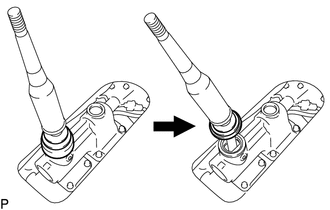
Detach the shift lever cap boot from the manual transmission.
-
Cover the shift lever cap with a cloth.
-
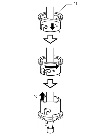
*1 Shift Lever Cap *a Press Down *b Counterclockwise *c Pull Out While pressing down on the shift lever cap, turn it counterclockwise, and then pull to remove the shift lever.
-
-
REMOVE NO. 1 FLOOR SHIFT BUSH
-
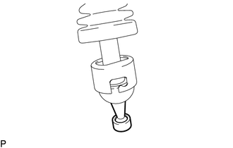
Remove the No. 1 floor shift bush from the floor shift shift lever assembly.
-
-
DRAIN MANUAL TRANSMISSION OIL
-
REMOVE NO. 1 ENGINE UNDER COVER ASSEMBLY
-
REMOVE NO. 2 ENGINE UNDER COVER
-
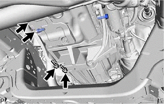
REMOVE PROPELLER SHAFT GUARD
-
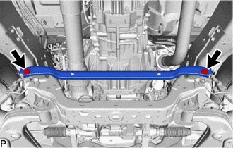
Remove the propeller shaft guard with the 2 bolts.
-
-
INSTALL FRONT EXHAUST PIPE ASSEMBLY (for 1GD-FTV)
-
INSTALL FRONT EXHAUST PIPE ASSEMBLY (for 2GD-FTV)
-
INSTALL FRONT EXHAUST PIPE ASSEMBLY (for 1KD-FTV)
-
REMOVE FRONT EXHAUST PIPE ASSEMBLY (for 2KD-FTV)
-
REMOVE UREA TANK SUB-ASSEMBLY (w/ Urea SCR System)
-
REMOVE STARTER ASSEMBLY (for 1GD-FTV)
-
for 2.0 kW Type:
-
for 2.2 kW Type:
-
for BOSCH Made:
-
-
REMOVE STARTER ASSEMBLY (for 2GD-FTV)
-
for 2.0 kW Type:
-
for 2.2 kW Type:
-
for 2.7 kW Type:
-
for BOSCH Made:
-
w/ Stop and Start System:
-
-
REMOVE STARTER ASSEMBLY (for 1KD-FTV)
-
for 2.0 kW Type:
-
for 2.2 kW Type:
-
for BOSCH Made:
-
-
REMOVE STARTER ASSEMBLY (for 2KD-FTV)
-
for 2.0 kW Type:
-
for 2.2 kW Type:
-
for 2.7 kW Type:
-
for BOSCH Made:
-
-
REMOVE NO. 4 CYLINDER BROCK INSULATOR
-
Remove the No. 4 cylinder block insulator.
-
-
REMOVE STIFFENER PLATE LH
-
Remove the 4 bolts and stiffener plate LH.
-
-
REMOVE STIFFENER PLATE RH
-
Remove the 4 bolts and stiffener plate RH.
-
-
REMOVE PROPELLER SHAFT WITH CENTER BEARING ASSEMBLY
-
for TMT Made:
-
for TSAM Made:
-
-
REMOVE FRONT DIFFERENTIAL CARRIER ASSEMBLY
-
DISCONNECT GROUND CABLE
-
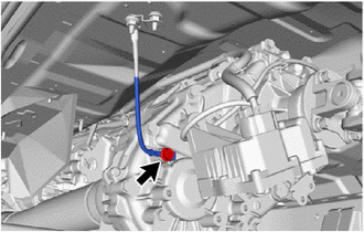
Remove the bolt and disconnect the ground cable.
-
-
SUPPORT MANUAL TRANSMISSION ASSEMBLY
-
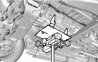
Support the manual transmission with a transmission jack.
Note
-
Make sure the high transmission jack attachment is centered on the safety stand.
-
Secure the part with a rope, attachment, etc.
-
-
-
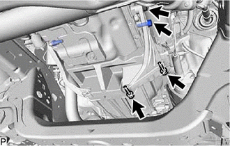
REMOVE NO. 3 FRAME CROSSMEMBER SUB-ASSEMBLY
-
Remove the 4 bolts from the No. 3 frame crossmember sub-assembly.
-
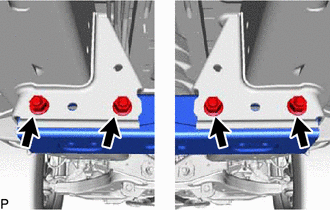
Remove the 4 nuts, 4 bolts and No. 3 frame crossmember sub-assembly.
-
-
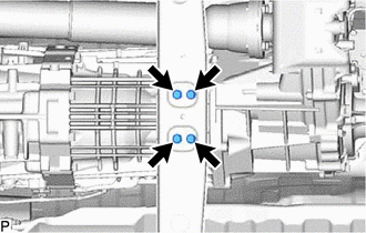
REMOVE REAR ENGINE MOUNTING INSULATOR
-
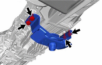
Remove the 4 bolts and rear engine mounting insulator from the manual transmission assembly.
-
-
DISCONNECT WIRE HARNESS
-
w/ Stop and Start System:
-
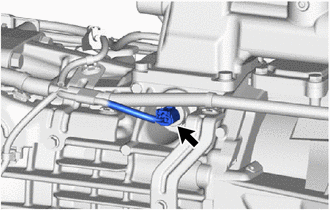
Disconnect the neutral position switch conector.
-
-
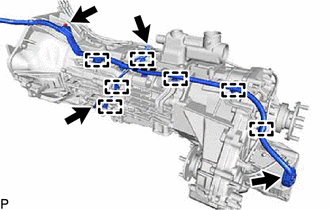
w/ Intelligent Manual Transmission Switch:
-
Detach the 7 wire harness clamps.
-
Remove the bolt.
-
Disconnect the 3 connectors and wire harness.
-
-
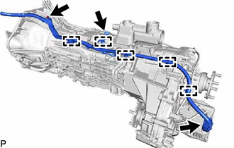
w/o Intelligent Manual Transmission Switch:
-
Detach the 5 wire harness clamps.
-
Remove the bolt.
-
Disconnect the 2 connectors and wire harness.
-
-
-
REMOVE MANUAL TRANSMISSION ASSEMBLY
-
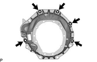
Remove the 5 bolts and manual transmission assembly.
Note
As the manual transmission assembly is very heavy, be sure to support it securely.
-
-
REMOVE TRANSMISSION BREATHER SUB-ASSEMBLY
-
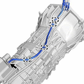
Detach the 4 breather hose clamps and bracket.
-
Remove the transmission breather sub-assembly from the control shift lever retainer assembly.
-
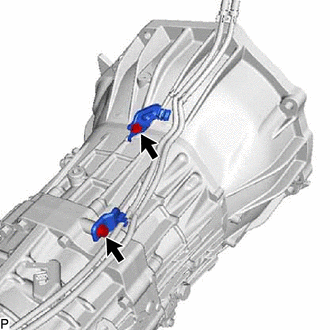
Remove the 2 bolts and 2 brackets.
-
-
REMOVE WIRING HARNESS CLAMP BRACKET
-
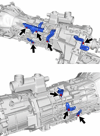
w/ Intelligent Manual Transmission Switch:
-
Remove the 8 bolts and 7 wiring harness clamp brackets.
-
-
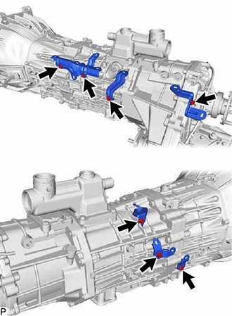
w/o Intelligent Manual Transmission Switch:
-
Remove the 7 bolts and 6 wiring harness clamp brackets.
-
-
-
REMOVE TRANSFER ASSEMBLY