REAR AIR CONDITIONING PANEL REMOVAL
CAUTION / NOTICE / HINT
The necessary procedures (adjustment, calibration, initialization or registration) that must be performed after parts are removed, installed or replaced during the rear power seat switch removal/installation are shown below.
| Replaced Part or Performed Procedure | Necessary Procedure | Effect/Inoperative Function when Necessary Procedure not Performed | Link |
|---|---|---|---|
| Disconnect cable from negative battery terminal | Drive the vehicle until stop and start control is permitted (approximately 5 to 60 minutes) | Stop and start system | for 8GR-FKS: Click here for V35A-FTS: Click here |
| Memorize steering angle neutral point | LKA/LDA system | ||
| Parking support brake system* | |||
| Pre-collision system | |||
| Adaptive high beam system | |||
Lighting system (EXT) |
|||
| Variable gear ratio steering system | |||
| Parking assist monitor system | |||
| Panoramic view monitor system | |||
| Initialize rear door sunshade system | Rear door sunshade system | ||
| Initialize power trunk lid system | Power trunk lid system | ||
| Steering sensor (Including removal and installation) | Steering angle neutral point | Parking support brake system | |
| Parking assist monitor system | |||
| Panoramic view monitor system | |||
| Steering angle setting | Parking assist monitor system | ||
| Panoramic view monitor system |
Click here Click here
Tech Tips
-
Use the same procedure for RHD and LHD vehicles.
-
The procedure listed below is for LHD vehicles.
PROCEDURE
-
PRECAUTION
Note
After turning the engine switch off, waiting time may be required before disconnecting the cable from the negative (-) battery terminal. Therefore, make sure to read the disconnecting the cable from the negative (-) battery terminal notices before proceeding with work.
-
REMOVE LUGGAGE COMPARTMENT MAT SUB-ASSEMBLY
-
DISCONNECT CABLE FROM NEGATIVE BATTERY TERMINAL
-
for 8GR-FKS:
-
for V35A-FTS:
Note
When disconnecting the cable, some systems need to be initialized after the cable is reconnected.
-
-
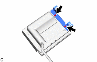
REMOVE NO. 2 REAR SEAT CENTER ARMREST PANEL SUB-ASSEMBLY
-
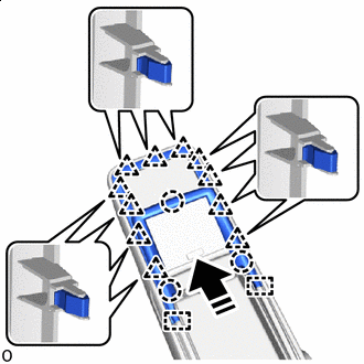

Remove in this Direction Detach the clip and claw.
-
While moving the No. 2 rear seat center armrest panel sub-assembly in the direction indicated by the arrow shown in the illustration, detach the guide to remove it.
-
-
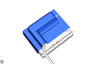
REMOVE NO. 2 REAR SEAT CENTER ARMREST PANEL
-
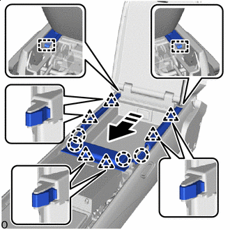
Remove in this Direction Detach the clip and claw.
-
While moving the No. 2 rear seat center armrest panel in the direction indicated by the arrow shown in the illustration, detach the guide to remove it.
-
-
REMOVE REAR POWER SEAT SWITCH WITH BRACKET
-
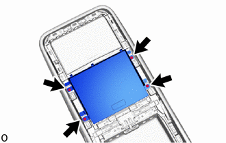
Remove the 4 screws and disconnect the rear power seat switch with bracket from the rear seat center armrest assembly.
-
-
REMOVE REAR SEAT CENTER ARMREST BRACKET RH
-
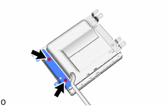
Remove the 2 screws and rear seat center armrest bracket RH.
-
-
REMOVE REAR SEAT CENTER ARMREST BRACKET LH
-
Remove the 2 screws and rear seat center armrest bracket LH.
-
-
REMOVE REAR SEAT CENTER ARMREST COVER
-
Remove the rear seat center armrest cover.
-
-
REMOVE REAR POWER SEAT SWITCH
-
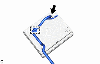
Disconnect the connector, detach the clamp and remove the rear power seat switch.
-