STEERING PAD REMOVAL

CAUTION / NOTICE / HINT
The necessary procedures (adjustment, calibration, initialization or registration) that must be performed after parts are removed, installed or replaced during the horn button assembly removal/installation are shown below.
| Replacement Part or Procedure | Necessary Procedures | Effects / Inoperative when not Performed | Link |
|---|---|---|---|
| Disconnect cable from negative (-) battery terminal | Drive the vehicle until stop and start control is permitted (approximately 5 to 60 minutes) | Stop and start system | for 8GR-FKS: for V35A-FTS: |
| Memorize steering angle neutral point | LKA/LDA system | ||
| Parking support brake system* | |||
| Pre-collision system | |||
| Adaptive high beam system | |||
Lighting system (EXT) |
|||
| Variable gear ratio steering system | |||
| Parking assist monitor system | |||
| Panoramic View Monitor system | |||
| Initialize Rear Door Sunshade System | Rear door sunshade system | ||
| Initialize power trunk lid system | Power trunk lid system |
Click here Click here
Tech Tips
-
Use the same procedure for RHD and LHD vehicles.
-
The procedure listed below is for LHD vehicles.
PROCEDURE
-
PRECAUTION
Note
After turning the engine switch off, waiting time may be required before disconnecting the cable from the negative (-) battery terminal. Therefore, make sure to read the disconnecting the cable from the negative (-) battery terminal notices before proceeding with work.
-
REMOVE LUGGAGE COMPARTMENT MAT SUB-ASSEMBLY
-
DISCONNECT CABLE FROM NEGATIVE BATTERY TERMINAL
for 8GR-FKS:
for V35A-FTS:
CAUTION:
-
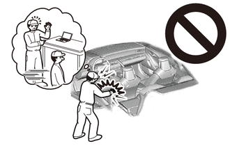
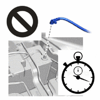
Wait at least 90 seconds after disconnecting the cable from the negative (-) battery terminal to disable the SRS system.
-
If the airbag deploys for any reason, it may cause a serious accident.
Note
When disconnecting the cable, some systems need to be initialized after the cable is reconnected.
-
-
REMOVE LOWER NO. 2 STEERING WHEEL COVER
-
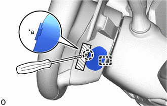
*a Cutout 
Protective Tape Using a screwdriver, insert the screwdriver into the cutout of the lower No. 2 steering wheel cover and detach the claw and guide to remove the lower No. 2 steering wheel cover.
Tech Tips
Tape the screwdriver tip before use.
-
-
REMOVE LOWER NO. 3 STEERING WHEEL COVER
-
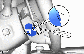
*a Cutout Protective Tape Using a screwdriver, insert the screwdriver into the cutout of the lower No. 3 steering wheel cover and detach the claw and guide to remove the lower No. 3 steering wheel cover.
Tech Tips
Tape the screwdriver tip before use.
-
-
REMOVE HORN BUTTON ASSEMBLY
CAUTION:
-
When storing the horn button assembly, keep the airbag deployment side facing upward.
-
If the airbag deploys for any reason, it may cause a serious accident.
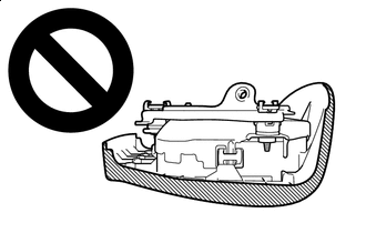
Deployment Side
-
Check that the engine switch is off.
-
Check that the cable is disconnected from the negative (-) battery terminal.
CAUTION:
-
Wait at least 90 seconds after disconnecting the cable from the negative (-) battery terminal to disable the SRS system.
-
If the airbag deploys for any reason, it may cause a serious accident.
-
-
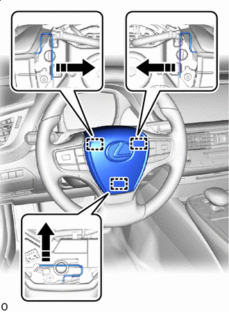

Release in this Direction Using a screwdriver, push the torsion spring to detach the pin.
Tech Tips
Insert the screwdriver into the installation areas of the lower No. 2 steering wheel cover and lower No. 3 steering wheel cover.
-
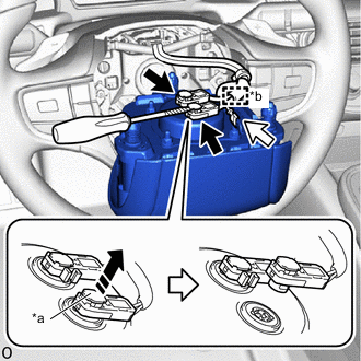
*a Lock Button *b Wire Harness Clamp 
Airbag connector 
Horn connector Release in this Direction Protective Tape Tilt the horn button assembly toward the seat and support it with one hand.
Note
-
Do not drop the horn button assembly.
-
When disconnecting the horn button assembly, do not pull the airbag wire harness.
-
-
Using a screwdriver, release the lock button and disconnect the airbag connector.
Note
When disconnecting any airbag connector, take care not to damage the airbag wire harness.
Tech Tips
-
Use the same procedure for the opposite side.
-
Tape the screwdriver tip before use.
-
-
Detach the wire harness clamp and disconnect the horn connector.
-