SHIFT CONTROL ECU REMOVAL
CAUTION / NOTICE / HINT
The necessary procedures (adjustment, calibration, initialization or registration) that must be performed after parts are removed and installed, or replaced during shift control ECU removal/installation are shown below.
| Replacement Part or Procedure | Necessary Procedure | Effect/Inoperative when not Performed | Link |
|---|---|---|---|
| Disconnect cable from negative battery terminal | Drive the vehicle until stop and start control is permitted (approximately 5 to 60 minutes) | Stop and start system | for 8GR-FKS: Click here for V35A-FTS: Click here |
| Memorize steering angle neutral point | LKA/LDA system | ||
| Parking support brake system* | |||
| Pre-collision system | |||
| Adaptive high beam system | |||
Lighting system (EXT) |
|||
| Variable gear ratio steering system | |||
| Parking assist monitor system | |||
| Panoramic view monitor system | |||
| Initialize rear door sunshade system | Rear door sunshade system | ||
| Initialize power trunk lid system | Power trunk lid system |
Click here Click here
Note
After the engine switch is turned off, the navigation system requires approximately a minute to record various types of memory and settings. As a result, after turning the engine switch off, wait a minute or more before disconnecting the cable from the negative (-) battery terminal.
PROCEDURE
-
PRECAUTION
Note
After turning the engine switch off, waiting time may be required before disconnecting the cable from the negative (-) battery terminal. Therefore, make sure to read the disconnecting the cable from the negative (-) battery terminal notices before proceeding with work.
-
REMOVE LUGGAGE COMPARTMENT MAT SUB-ASSEMBLY
-
REMOVE TOOL BOX (for 8GR-FKS)
-
REMOVE TOOL BOX (for V35A-FTS)
-
DISCONNECT CABLE FROM NEGATIVE BATTERY TERMINAL
Note
It is necessary to remove the shift control ECU while no power is being supplied from the sub-battery. Therefore, perform the following procedures.
-
Turn the engine switch off.
-
Check that the ODO meter display has turned off.
Tech Tips
The ODO meter continues to display for 30 seconds after turning off. Therefore, allow sufficient time for the shift control ECU to enter sleep mode and for the sub-battery power supply to end. In addition to monitoring the sub-battery voltage directly, the only other method for checking on the vehicle is to use the ODO meter display.
-
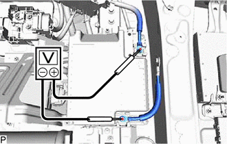
Check that the voltage between the terminals of the sub-battery assembly with control is 0 V.
for 8GR-FKS: Click here
for V35A-FTS: Click here
-
Disconnect the cable from the negative (-) battery terminal.
Note
When disconnecting the cable, some systems need to be initialized after the cable is reconnected.
-
-
REMOVE GLOVE COMPARTMENT DOOR ASSEMBLY
-
REMOVE NO. 2 AIR DUCT SUB-ASSEMBLY
-
REMOVE SHIFT CONTROL ECU
-
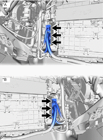
*A for LHD *B for RHD Disconnect the 3 shift control ECU connectors.
-
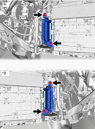
*A for LHD *B for RHD Remove the 2 bolts and shift control ECU.
-
-
REMOVE NO. 1 SHIFT CONTROL ECU BRACKET
-
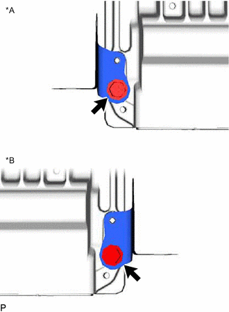
*A for LHD *B for RHD Remove the bolt and No. 1 shift control ECU bracket from the shift control ECU.
-
-
REMOVE NO. 2 SHIFT CONTROL ECU BRACKET
-
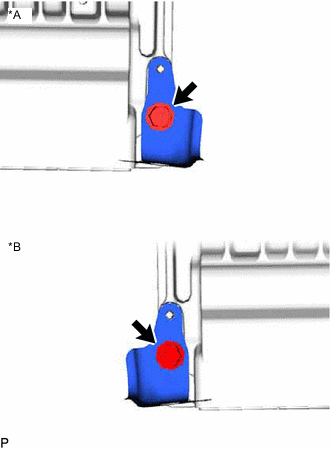
*A for LHD *B for RHD Remove the bolt and No. 2 shift control ECU bracket from the shift control ECU.
-