OIL COOLER(for 8GR-FKS) INSTALLATION
PROCEDURE
-
INSTALL OIL COOLER BRACKET
-
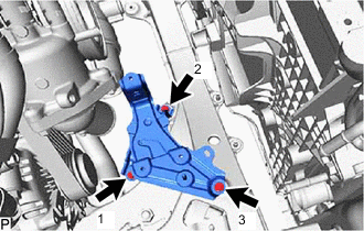
Install the oil cooler bracket with the 3 bolts.
- Torque:
- 8.0 N*m { 82 kgf*cm, 71 in.*lbf }
Tech Tips
Tighten the bolts in the tightening order shown in the illustration.
-
-
INSTALL OIL COOLER ASSEMBLY
-
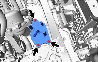
Install the oil cooler assembly with the 3 bolts.
- Torque:
- 8.0 N*m { 82 kgf*cm, 71 in.*lbf }
Tech Tips
Tighten the bolts in the tightening order shown in the illustration.
-
-
INSTALL NO. 1 WATER BY-PASS HOSE (w/o In-tank Oil Cooler)
-
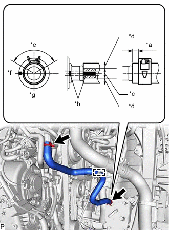
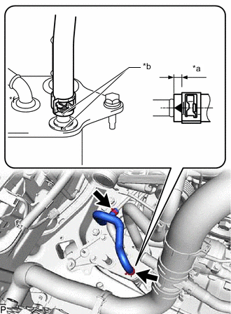
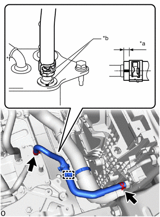
*a 2.0 to 7.0 mm (0.0787 to 0.276 in.) *b Paint Mark *c Permissible range for paint mark position *d Outside permissible range for paint mark position *e Clamp Range 120° *f Front of Vehicle *g Left side of Vehicle Install the No. 1 water by-pass hose to the oil cooler assembly and water outlet sub-assembly, and slide the 2 hose clips to secure the hose.
Note
-
The hose clip claw position is within the range shown in the illustration.
-
Do not deform the oil cooler assembly.
-
Install the No. 1 water by-pass hose so that its paint marks are within the allowable range (3 paint lines) of the paint marks of the oil cooler assembly.
-
When installing the No. 1 water by-pass hose, do not twist the No. 1 water by-pass hose.
-
-
Attach the No. 1 water by-pass hose to the clamp.
-
-
INSTALL NO. 1 OIL COOLER INLET HOSE (w/o In-tank Oil Cooler)
-
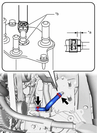
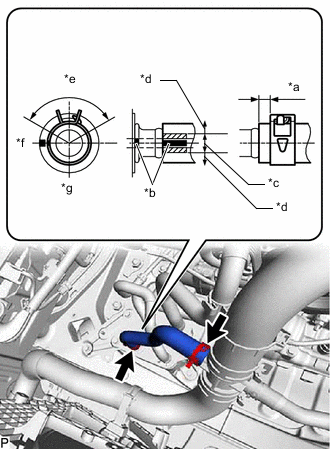
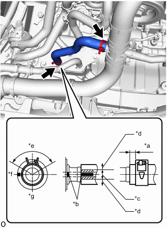
*a 2.0 to 7.0 mm (0.0787 to 0.276 in.) *b Paint Mark Install the No. 1 oil cooler inlet hose to the No. 1 oil cooler inlet tube and oil cooler assembly, and slide the 2 hose clips to secure the hose.
Note
-
Do not deform the oil cooler assembly.
-
When connecting the hose, align with the colors and positions of the paint mark before connecting.
-
When installing the No. 1 oil cooler inlet hose, do not twist the No. 1 oil cooler inlet hose.
-
-
-
INSTALL NO. 1 OIL COOLER OUTLET HOSE (w/o In-tank Oil Cooler)
-
*a 2.0 to 7.0 mm (0.0787 to 0.276 in.) *b Paint Mark Install the No. 1 oil cooler outlet hose to the oil cooler assembly and No. 1 oil cooler outlet tube, and slide the 2 hose clips to secure the hose.
Note
-
The hose clip claw position is within the range shown in the illustration.
-
Do not deform the oil cooler assembly.
-
When installing the No. 1 oil cooler outlet hose, align with the colors and positions of the paint mark before connecting.
-
When installing the No. 1 oil cooler outlet hose, do not twist the No. 1 oil cooler outlet hose.
-
-
-
INSTALL WATER INLET HOSE (w/o In-tank Oil Cooler)
-
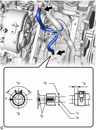
*a 2.0 to 7.0 mm (0.0787 to 0.276 in.) *b Paint Mark *c Permissible range for paint mark position *d Outside permissible range for paint mark position *e Clamp Range 120° *f Front of Vehicle *g Left side of Vehicle Install the water inlet hose to the No. 3 radiator hose and oil cooler assembly, and slide the 2 hose clips to secure the hose.
Note
-
Do not deform the oil cooler assembly.
-
When connecting the water inlet hose, align with the colors and positions of the paint mark before connecting.
-
When installing the water inlet hose, do not twist the water inlet hose.
-
-
-
INSTALL HEATER ACCESSORY ASSEMBLY (w/o In-tank Oil Cooler)
-
INSTALL NO. 1 WATER BY-PASS HOSE (w/ In-tank Oil Cooler)
-
*a 2.0 to 7.0 mm (0.0787 to 0.276 in.) *b Paint Mark *c Permissible range for paint mark position *d Outside permissible range for paint mark position *e Clamp Range 120° *f Front of Vehicle *g Left side of Vehicle Install the No. 1 water by-pass hose to the oil cooler assembly and water outlet sub-assembly, and slide the 2 hose clips to secure the hose.
Note
-
The hose clip claw position is within the range shown in the illustration.
-
Do not deform the oil cooler assembly.
-
Install the No. 1 water by-pass hose so that its paint marks are within the allowable range (3 paint lines) of the paint marks of the oil cooler assembly.
-
When installing the No. 1 water by-pass hose, do not twist the No. 1 water by-pass hose.
-
-
Attach the No. 1 water by-pass hose to the clamp.
-
-
INSTALL NO. 1 OIL COOLER INLET HOSE (w/ In-tank Oil Cooler)
-
*a 2.0 to 7.0 mm (0.0787 to 0.276 in.) *b Paint Mark Install the No. 1 oil cooler inlet hose to the No. 1 oil cooler inlet tube and oil cooler assembly, and slide the 2 hose clips to secure the hose.
Note
-
Do not deform the oil cooler assembly.
-
When connecting the hose, align with the colors and positions of the paint mark before connecting.
-
When installing the No. 1 oil cooler inlet hose, do not twist the No. 1 oil cooler inlet hose.
-
-
-
INSTALL NO. 1 TRANSMISSION OIL COOLER HOSE (w/ In-tank Oil Cooler)
-
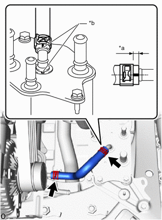
*a 2.0 to 7.0 mm (0.0787 to 0.276 in.) *b Paint Mark Install the No. 1 transmission oil cooler hose to the oil cooler assembly and radiator assembly, and slide the 2 hose clips to secure the hose.
Note
-
Do not deform the oil cooler assembly.
-
When installing the No. 1 transmission oil cooler hose, do not twist the No. 1 transmission oil cooler hose.
-
Install the No. 1 transmission oil cooler hose so that its paint marks are within the allowable range (3 paint lines) of the paint marks of the oil cooler assembly.
-
-
Attach the No. 1 transmission oil cooler hose to the clamp.
-
-
INSTALL HEATER ACCESSORY ASSEMBLY (w/ In-tank Oil Cooler)
-
INSTALL WATER INLET HOSE (w/ In-tank Oil Cooler)
-
*a 2.0 to 7.0 mm (0.0787 to 0.276 in.) *b Paint Mark *c Permissible range for paint mark position *d Outside permissible range for paint mark position *e Clamp Range 120° *f Front of Vehicle *g Left side of Vehicle Install the water inlet hose to the No. 3 radiator hose and oil cooler assembly, and slide the 2 hose clips to secure the hose.
Note
-
The hose clip claw position is within the range shown in the illustration.
-
Do not deform the oil cooler assembly.
-
When connecting the water inlet hose, align with the colors and positions of the paint mark before connecting.
-
When installing the water inlet hose, do not twist the water inlet hose.
-
-
-
INSTALL NO. 1 OIL COOLER OUTLET HOSE (w/ In-tank Oil Cooler)
-
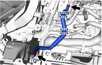
Install the No. 1 oil cooler outlet hose to the No. 1 oil cooler outlet tube and radiator assembly, and slide the 2 hose clips to secure the hose.
Note
-
When connecting the hose, align with the colors and positions of the paint mark before connecting.
-
When installing the No. 1 oil cooler outlet hose, do not twist the No. 1 oil cooler outlet hose.
-
-
Attach the 2 clamps and connect the No. 1 oil cooler outlet hose to the No. 1 transmission oil cooler hose and water hose sub-assembly.
-
-
INSTALL RADIATOR RESERVE TANK ASSEMBLY
-
INSTALL AIR CLEANER ASSEMBLY
-
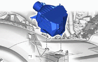
*1 Air Cleaner Support Install the air cleaner assembly to the 3 air cleaner supports.
-
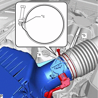
*a Protrusion *b Cutout *c Stopper Align the protrusion of the air cleaner assembly with the cutout of the air cleaner hose assembly, and connect the air cleaner hose assembly to the air cleaner assembly.
-
Tighten while pressing the hose clamp against the stopper on the air cleaner hose assembly.
- Torque:
- 4.0 N*m { 41 kgf*cm, 35 in.*lbf }
-
Connect the intake mass air flow meter connector.
-
Attach the wire harness clamp.
-
-
INSTALL NO. 1 AIR CLEANER INLET
-
INSTALL RADIATOR SUPPORT TO CROSS MEMBER BRACE SUB-ASSEMBLY RH
-
ADD ENGINE COOLANT
-
INSTALL LOWER RADIATOR AIR DEFLECTOR
-
INSTALL UPPER RADIATOR SUPPORT SEAL
-
INSTALL RADIATOR COVER PLATE
-
INSTALL V-BANK COVER SUB-ASSEMBLY
-
ADD AUTOMATIC TRANSMISSION FLUID
-
ADJUST AUTOMATIC TRANSMISSION FLUID
-
INSPECT FOR COOLANT LEAK
-
INSTALL STRUT BAR BRACKET SUPPORT SUB-ASSEMBLY
-
INSTALL FRONT SUSPENSION MEMBER BRACE
-
INSTALL NO. 2 ENGINE UNDER COVER ASSEMBLY
-
INSTALL TRANSMISSION UNDER COVER
-
INSTALL NO. 1 ENGINE UNDER COVER ASSEMBLY
-
AFTER FILLING AUTOMATIC TRANSMISSION
-
ATF THERMAL DEGRADATION ESTIMATE RESET
Note
Approximately 50% or more of the ATF has been replaced during a repair of the transmission or a similar operation.