WATER CONTROL VALVE REMOVAL
CAUTION / NOTICE / HINT
Tech Tips
-
Use the same procedure for RHD and LHD vehicles.
-
The procedure listed below is for LHD vehicles.
The necessary procedures (adjustment, calibration, initialization, or registration) that must be performed after parts are removed, installed, or replaced during the water control valve removal/installation are shown below.
| Replacement Part or Procedure | Necessary Procedure | Effect/Inoperative when not Performed | Link |
|---|---|---|---|
| Disconnect cable from negative battery terminal | Drive the vehicle until stop and start control is permitted (approximately 5 to 60 minutes) | Stop and start system | |
| Memorize steering angle neutral point | LKA/LDA system | ||
| Parking support brake system* | |||
| Pre-collision system | |||
| Adaptive high beam system | |||
Lighting system (EXT) |
|||
| Variable gear ratio steering system | |||
| Parking assist monitor system | |||
| Panoramic view monitor system | |||
| Initialize rear door sunshade system | Rear door sunshade system | ||
| Initialize power trunk lid system | Power trunk lid system |
Click here Click here
Note
After the engine switch is turned off, the navigation system requires approximately a minute to record various types of memory and settings. As a result, after turning the engine switch off, wait a minute or more before disconnecting the cable from the negative (-) battery terminal.
| System Name | See Procedure |
|---|---|
| Vehicle enrolled in lexus enform system or safety connect system | 6 minutes |
| Vehicle not enrolled in lexus enform system and safety connect system | 1 minute |
Note
This procedure includes the removal of small-head bolts. Refer to Small-Head Bolts of Basic Repair Hint to identify the small-head bolts.
PROCEDURE
-
PRECAUTION
Note
After turning the engine switch off, waiting time may be required before disconnecting the cable from the negative (-) battery terminal. Therefore, make sure to read the disconnecting the cable from the negative (-) battery terminal notices before proceeding with work.
-
REMOVE LUGGAGE COMPARTMENT MAT SUB-ASSEMBLY
-
REMOVE LUGGAGE COMPARTMENT FLOOR MAT
-
DISCONNECT CABLE FROM NEGATIVE BATTERY TERMINAL
Note
When disconnecting the cable, some systems need to be initialized after the cable is reconnected.
Tech Tips
A DTC may be output if the water control valve is removed or installed with the negative (-) battery terminal connected. Therefore, make sure to disconnect the negative (-) battery terminal before removing or installing the water control valve.
-
REMOVE NO. 1 ENGINE UNDER COVER ASSEMBLY
-
for 2WD:
-
for AWD:
-
-
REMOVE OIL PAN PROTECTOR (for 2WD)
-
REMOVE FRONT SUSPENSION MEMBER BRACE (for AWD)
-
REMOVE STRUT BAR BRACKET SUPPORT SUB-ASSEMBLY (for AWD)
-
REMOVE V-BANK COVER SUB-ASSEMBLY
-
REMOVE UPPER RADIATOR SUPPORT SEAL
-
REMOVE RADIATOR COVER PLATE
-
REMOVE LOWER RADIATOR AIR DEFLECTOR
-
DRAIN ENGINE COOLANT
-
DISCONNECT ENGINE WIRE
-
Disconnect the connectors.
-
Detach the clamp and disconnect the engine wire.
-
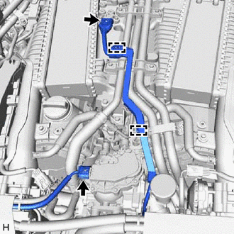
Disconnect the connectors.
-
Detach the clamps and disconnect the engine wire.
-
-
REMOVE NO. 1 TURBO PRESSURE SENSOR (for Bank 1)
-
REMOVE INTAKE PIPE STAY
-
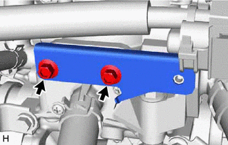
Remove the 2 bolts and intake pipe stay.
-
-
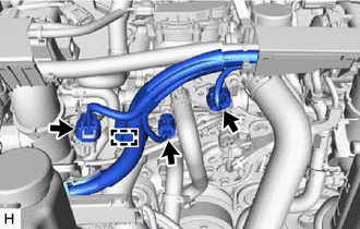
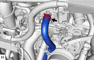
DISCONNECT NO. 3 RADIATOR HOSE
-
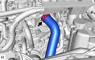
Slide the clip and disconnect the No. 3 radiator hose from the water control valve.
-
-
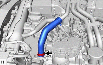
DISCONNECT NO. 1 WATER BY-PASS HOSE
-
Slide the clip and disconnect the No. 1 water by-pass hose from the water control valve.
-
-
DISCONNECT NO. 2 WATER BY-PASS HOSE
-
Slide the clip and disconnect the No. 2 water by-pass hose from the water control valve.
-
-
DISCONNECT NO. 3 WATER BY-PASS HOSE
-
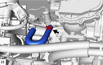
Slide the clip and disconnect the No. 3 water by-pass hose from the water control valve.
-
-
REMOVE WATER FILLER CAP SUB-ASSEMBLY
-
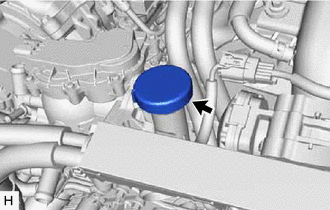
Remove the water filler cap sub-assembly from the water control valve.
-
-
REMOVE WATER CONTROL VALVE
-
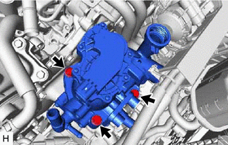
Remove the 3 bolts and water control valve.
-
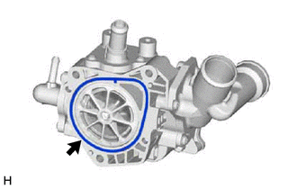
Remove the water outlet housing gasket from the water control valve.
-