WATER PUMP INSTALLATION

CAUTION / NOTICE / HINT
Tech Tips
-
Use the same procedure for RHD and LHD vehicles.
-
The procedure listed below is for LHD vehicles.
PROCEDURE
-
INSTALL ENGINE WATER PUMP ASSEMBLY
-
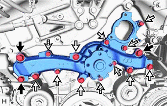

Bolt A 
Bolt B 
Bolt C 
Bolt D Install a new water pump gasket and engine water pump assembly with the 15 bolts.
Adhesive Toyota Genuine Adhesive 1344, Three Bond 1344 or equivalent - Torque:
- for bolt A
- 43 N*m { 438 kgf*cm, 32 ft.*lbf }
- for bolt B
- 21 N*m { 214 kgf*cm, 15 ft.*lbf }
- for bolt C and D
- 11 N*m { 112 kgf*cm, 8 ft.*lbf }
Standard Length Item Length Bolt A 60 mm (2.36 in.) Bolt B 55 mm (2.17 in.) Bolt C, D 22 mm (0.866 in.) Note
-
Make sure that there is no oil on the threads of the bolts A and B.
-
Be sure to replace the 2 bolts D with new ones or reuse them after applying adhesive.
-
Do not start the engine for at least 1 hour after installation.
-
-
INSTALL WATER PUMP PULLEY
-
Temporarily install the water pump pulley with the 4 bolts.
-
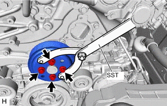
Using SST, hold the water pump pulley.
- SST
- 09960-10010 ( 09962-01000, 09963-00700 )
-
Tighten the 4 bolts.
- Torque:
- 21 N*m { 214 kgf*cm, 15 ft.*lbf }
-
-
INSTALL WATER INLET WITH THERMOSTAT SUB-ASSEMBLY
-
CONNECT WATER BY-PASS HOSE
-
INSTALL FAN AND GENERATOR V BELT
-
CONNECT OIL COOLER OUTLET HOSE
-
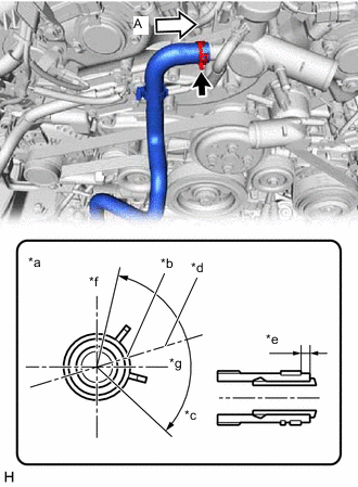
*a View A *b Paint Mark *c 120° *d Rib *e 2 to 7 mm (0.0787 to 0.276 in.) *f Upper Side *g Front Side Connect the oil cooler outlet hose to the water outlet sub-assembly, and slide the clip to secure the hose.
Note
-
Align the paint marks on the oil cooler outlet hose to the paint mark on the motor cooling cooler and rib of the water outlet sub-assembly.
-
Do not deform the motor cooling cooler.
-
Water or coolant can be used to assist with inserting the hose, however when using liquid other than water, dilute it to 50% concentration or less before use.
-
-
-
CONNECT WATER HOSE (for Heater)
-
*a Water Hose Marking *b Heater Accessory Assembly Marking Connect the water hose to the heater accessory assembly, and slide the clip to secure the hose.
-
Attach the clamp.
-
-
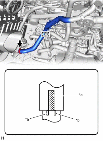
CONNECT WATER HOSE
-
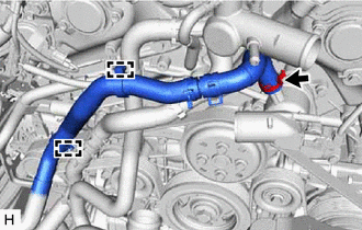
Connect the water hose to the water inlet with thermostat sub-assembly, and slide the clip to secure the hose.
Note
-
Position the clip so that it faces the same direction as the paint mark.
-
Position the clip so that is 1 to 5 mm (0.0394 to 0.197 in.) away from the end of the water hose.
-
-
Attach the clamps.
-
-
CONNECT NO. 3 RADIATOR HOSE
-
CONNECT NO. 1 RADIATOR HOSE
-
INSTALL NO. 1 AIR CLEANER INLET
-
INSTALL RADIATOR SUPPORT TO CROSSMEMBER BRACE SUB-ASSEMBLY LH
-
INSTALL RADIATOR SUPPORT TO CROSSMEMBER BRACE SUB-ASSEMBLY RH
-
ADD ENGINE COOLANT
-
INSPECT FOR COOLANT LEAK
-
INSTALL LOWER RADIATOR AIR DEFLECTOR
-
INSTALL UPPER RADIATOR SUPPORT SEAL
-
INSTALL RADIATOR COVER PLATE
-
INSTALL V-BANK COVER SUB-ASSEMBLY
-
INSTALL OIL PAN PROTECTOR
-
INSTALL NO. 1 ENGINE UNDER COVER ASSEMBLY