ENGINE OIL COOLER (w/ EGR Cooler) INSTALLATION
Note
-
When replacing the injectors (including shuffling the injectors between the cylinders), common rail or cylinder head, it is necessary to replace the injection pipes with new ones.
-
When replacing the fuel supply pump, common rail, cylinder block, cylinder head, cylinder head gasket or timing gear case, it is necessary to replace the fuel inlet pipe with a new one.
-
INSTALL OIL COOLER ASSEMBLY
-
Install 2 new gaskets to the oil cooler.
-
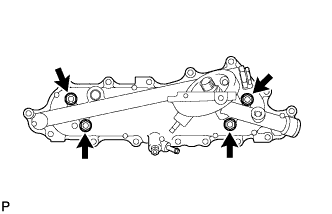
Install the oil cooler to the oil cooler cover with the 4 nuts.
- Torque:
- 16 N*m { 163 kgf*cm, 12 ft.*lbf }
-
-
INSTALL OIL COOLER COVER SUB-ASSEMBLY
-
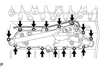
Install a new gasket and the oil cooler cover with the 13 bolts.
- Torque:
- 13 N*m { 133 kgf*cm, 10 ft.*lbf }
-
Install the No. 2 vacuum transmitting pipe with the 2 nuts.
- Torque:
- 13 N*m { 133 kgf*cm, 10 ft.*lbf }
-
Connect the oil pressure connector and wire harness.
-
-
INSTALL OIL FILTER SUB-ASSEMBLY
-
Check and clean the oil filter installation surface.
-
Apply clean engine oil to the gasket of a new oil filter.
-
Lightly screw the oil filter into place by hand. Tighten it until the gasket contacts the seat.
-
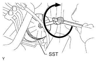
Using SST, tighten the oil filter. Depending on the work space available, choose from the following.
- SST
- 09228-07501
-
If enough space is available, use a torque wrench to tighten the oil filter.
- Torque:
- 12 N*m { 122 kgf*cm, 9 ft.*lbf }
-
If enough space is not available to use a torque wrench, tighten the oil filter 3/4 turn by hand or with a common wrench.
-
-
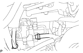
INSTALL FUEL SUPPLY PUMP ASSEMBLY
-
Check that the injection gear in the timing gear case moves back and forth smoothly.
-
Install a new O-ring to the pump.
-
Apply a light coat of engine oil to the O-ring.
-
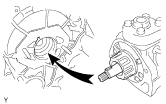
Align the set key on the drive shaft with the groove of the injection gear.
-
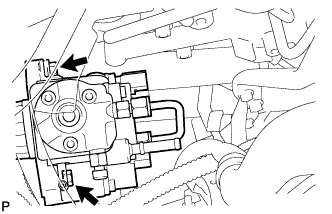
Install the pump with the 2 nuts.
- Torque:
- 21 N*m { 214 kgf*cm, 15 ft.*lbf }
-
Set a new O-ring.
-
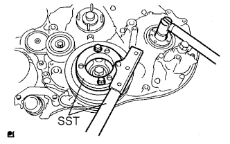
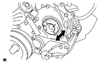
Using SST, hold the crankshaft pulley and install the set nut.
- SST
- 09213-58013
- 09330-00021
- Torque:
- 64 N*m { 653 kgf*cm, 47 ft.*lbf }
-
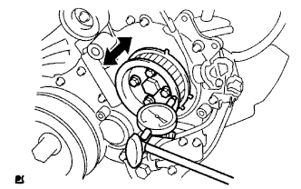
Using a dial indicator, measure the thrust clearance of the injection pump shaft by moving the pump drive shaft pulley back and forth.
Thrust clearance 0.15 to 0.55 mm (0.0059 to 0.0217 in.) If the clearance is not within the specified range, disassemble and reassemble the supply pump and pump drive shaft pulley. Then repeat the step above.
-
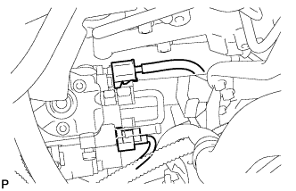
Connect the 2 connectors.
-
Connect the 2 fuel hoses.
-
-
INSTALL STARTER ASSEMBLY
-
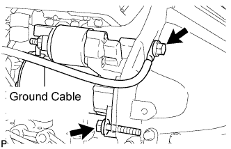
Connect the ground wire and install the starter with the 2 bolts.
Tech Tips
Make sure to connect the ground wire with the bolt as shown in the illustration.
- Torque:
- 68 N*m { 693 kgf*cm, 50 ft.*lbf }
-
Install the starter wire to terminal 30 with the nut.
- Torque:
- 9.8 N*m { 100 kgf*cm, 87 in.*lbf }
-
Connect the starter connector.
-
-
INSTALL COMMON RAIL ASSEMBLY
Note
When replacing the common rail, do not remove the foreign object mixing prevention caps of the common rail until just before the fuel inlet pipe and injection pipe are connected to the common rail.
-
Install the common rail and insulator with the 2 bolts.
- Torque:
- 38 N*m { 387 kgf*cm, 28 ft.*lbf }
-
Connect the 2 connectors.
-
-
INSTALL NO. 2 INTAKE MANIFOLD INSULATOR
-
INSTALL FUEL INLET PIPE SUB-ASSEMBLY
-
Temporarily install the fuel inlet pipe with the union nuts.
Note
-
If the supply pump is replaced, the fuel inlet pipe must be replaced.
-
Keep the fuel inlet pipe free of foreign matter.
-
-
Install a new O-ring to the oil level gauge guide, and install the oil level gauge guide to the cylinder block.
Note
Apply a coat of engine oil to the O-ring.
-
Temporarily install the stay of the oil level gauge guide to the intake manifold with the bolt.
-
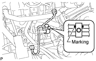
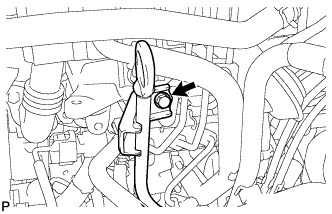
Install the clamp with the bolt.
Note
Install the clamp so that the fuel inlet pipe marking can be seen on both sides of the clamp.
- Torque:
- 5.0 N*m { 51 kgf*cm, 44 in.*lbf }
-
Tighten the bolt of the oil level gauge guide stay.
- Torque:
- 8.0 N*m { 82 kgf*cm, 71 in.*lbf }
-
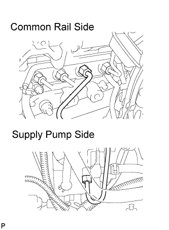
Using a 17 mm union nut wrench, tighten the injection pipe union nut on the common rail side.
- Torque:
- without union nut wrench
- 35 N*m { 357 kgf*cm, 26 ft.*lbf }
- with union nut wrench
- 32 N*m { 326 kgf*cm, 24 ft.*lbf }
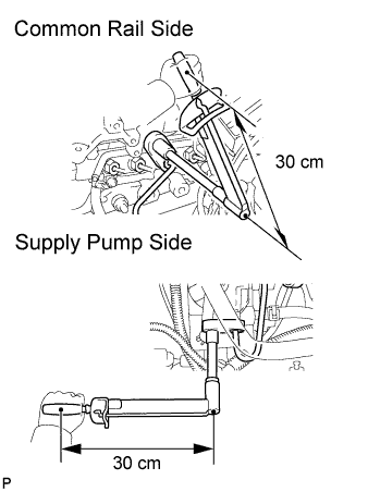
Tech Tips
-
Use a torque wrench with a fulcrum length of 30 cm (11.81 in.). If using a torque wrench with a length that is not 30 cm, calculate the torque specification for the torque wrench and union nut wrench based on the "without union nut wrench" torque specification Click here.
-
Make sure union nut wrench and wrench are connected in a straight line.
-
Using a 17 mm union nut wrench, tighten the injection pipe union nut on the supply pump side.
- Torque:
- without union nut wrench
- 35 N*m { 357 kgf*cm, 26 ft.*lbf }
- with union nut wrench
- 32 N*m { 326 kgf*cm, 24 ft.*lbf }
Tech Tips
-
Use a torque wrench with a fulcrum length of 30 cm (11.81 in.). If using a torque wrench with a length that is not 30 cm, calculate the torque specification for the torque wrench and union nut wrench based on the "without union nut wrench" torque specification Click here.
-
Make sure union nut wrench and wrench are connected in a straight line.
-
-
REMOVE NO. 2 NOZZLE LEAKAGE PIPE ASSEMBLY
-
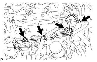
Temporarily install the leakage pipe with the 3 bolts.
-
Temporarily install a new gasket with the check valve.
-
Tighten the 3 bolts and check valve.
- Torque:
- check valve
- 21 N*m { 214 kgf*cm, 16 ft.*lbf }
- bolt
- 13 N*m { 133 kgf*cm, 10 ft.*lbf }
-
Connect the 3 fuel hoses.
-
-
INSTALL OIL DIPSTICK GUIDE
-
Install a new O-ring to the guide.
-
Apply a small amount of clean engine oil to the O-ring.
-
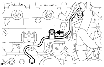
Install the guide with the bolt.
- Torque:
- 8.0 N*m { 82 kgf*cm, 71 in.*lbf }
-
Install the injection pipe clamp with the bolt.
- Torque:
- 5.0 N*m { 51 kgf*cm, 44 in.*lbf }
-
-
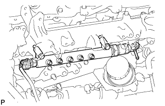
INSTALL NO. 4 INJECTION PIPE
Note
-
When replacing the injector, also replace the injection pipe.
-
Keep the joints of the injection pipe clean.
-
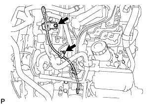
Temporarily install the No. 4 injection pipe with the union nuts.
-
Install new injection pipe clamp with the bolt.
- Torque:
- 5.0 N*m { 51 kgf*cm, 44 in.*lbf }
Note
-
Make sure that the inner-rubbers of the injection pipe fit inside the clamp.
-
When installing the pipe, check that the inner rubbers and the clamp are in their proper positions.
-
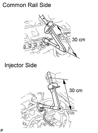
Using a 17 mm union nut wrench, tighten the injection pipe union nuts on the common rail side.
- Torque:
- without union nut wrench
- 35 N*m { 357 kgf*cm, 26 ft.*lbf }
- with union nut wrench
- 32 N*m { 326 kgf*cm, 24 ft.*lbf }
Tech Tips
-
Use a torque wrench with a fulcrum length of 30 cm (11.81 in.). If using a torque wrench with a length that is not 30 cm, calculate the torque specification for the torque wrench and union nut wrench based on the "without SST" torque specification Click here.
-
Make sure union nut wrench and wrench are connected in a straight line.
-
Using a union nut wrench, tighten the injection pipe union nuts on the injector side.
- Torque:
- without union nut wrench
- 35 N*m { 357 kgf*cm, 26 ft.*lbf }
- with union nut wrench
- 32 N*m { 326 kgf*cm, 24 ft.*lbf }
Tech Tips
-
Use a torque wrench with a fulcrum length of 30 cm (11.81 in.). If using a torque wrench with a length that is not 30 cm, calculate the torque specification for the torque wrench and union nut wrench based on the "without union nut wrench" torque specification Click here.
-
Make sure union nut wrench and wrench are connected in a straight line.
-
-
INSTALL EGR COOLER WITH ELECTRIC EGR CONTROL VALVE AND NO. 2 EGR VALVE
-
Install the EGR cooler with electric EGR control valve and No. 2 EGR valve Click here.
-
-
INSTALL MANIFOLD STAY
-
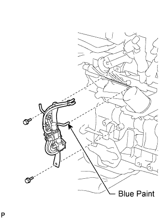
Install the manifold stay with VSV with the 2 bolts, and connect the No. 1 vacuum transmitting hose (color is "Blue") to the No. 2 vacuum transmitting pipe.
- Torque:
- 19 N*m { 194 kgf*cm, 14 ft.*lbf }
Note
Install the vacuum hoses so that they completely cover the pipes.
-
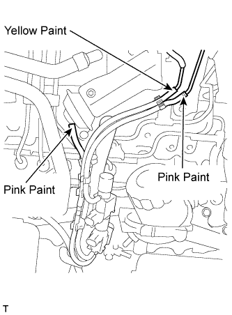
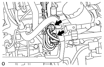
Connect the 3 vacuum hoses.
Note
-
Install the vacuum hoses so that they completely cover the pipes.
-
Make sure the vacuum hoses' color matches the connection areas' color.
-
-
Connect the 2 connectors.
-
-
ADD FUEL
-
INSTALL FUEL TANK CAP ASSEMBLY
-
BLEED AIR FROM FUEL SYSTEM
-
ADD ENGINE OIL
-
Wipe the oil pan and drain plug.
-
Install a new gasket and the drain plug.
- Torque:
- 34 N*m { 347 kgf*cm, 25 ft.*lbf }
-
Add new oil.
Standard oil capacity Item Specified Condition Drain and refill with oil filter change 6.9 liters (7.3 US qts, 6.1 Imp. qts) Drain and refill without oil filter change 6.6 liters (7.0 US qts, 5.8 Imp. qts) Dry fill 7.4 liters (7.8 US qts, 6.5 Imp. qts) -
Install the oil filler cap.
-
-
CONNECT CABLE TO NEGATIVE BATTERY TERMINAL
-
INSPECT FOR FUEL LEAK
CAUTION:
-
During Active Test mode, engine speed becomes high and combustion noise becomes loud, so pay attention.
-
During Active Test mode, fuel becomes high-pressured. Be extremely careful not to expose your eyes, hands, or body to escaped fuel.
-
Check that there are no leaks from any part of the fuel system when the engine is stopped. If there is fuel leakage, repair or replace parts as necessary.
-
Start the engine and check that there are no leaks from any part of the fuel system. If there is fuel leakage, repair or replace parts as necessary.
-
Disconnect the return hose from the common rail.
-
Start the engine and check for fuel leaks from the return pipe.
If there is fuel leakage, replace the common rail.
-
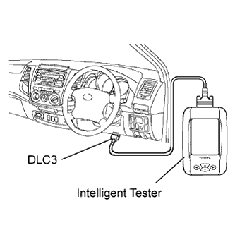
Connect the intelligent tester to the DLC3.
-
Start the engine and push the intelligent tester main switch ON.
-
Select the Fuel Leak test from the Active Test mode on the intelligent tester.
-
If the intelligent tester is not available, fully depress the accelerator pedal quickly. Increase the engine speed to the maximum and maintain that speed for 2 seconds. Repeat this operation several times.
-
Check that there are no leaks from any part of the fuel system.
Note
A return pipe leakage of less than 10 cc (0.6 cu in.) per minute is acceptable.
If there is fuel leakage, repair or replace parts as necessary.
-
Reconnect the return hose to the common rail.
-
-
ADD ENGINE COOLANT
-
Tighten the cylinder block drain cock plug.
- Torque:
- 8.0 N*m { 82 kgf*cm, 71 in.*lbf }
-
Tighten the radiator drain cock plug by hand.
-
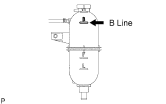
Fill the radiator with TOYOTA Super Long Life Coolant (SLLC) to the reservoir tank's B line.
Standard capacity Item Specified Condition A/T 11.1 liters (11.7 US qts, 9.8 Imp. qts) M/T 9.8 liters (10.4 US qts, 8.6 Imp. qts) Tech Tips
TOYOTA vehicles are filled with TOYOTA SLLC at the factory. In order to avoid damage to the engine cooling system and other technical problems, only use TOYOTA SLLC or similar high quality ethylene glycol based non-silicate, non-amine, non-nitrite, non-borate coolant with long-life hybrid organic acid technology (coolant with long-life hybrid organic acid technology consists of a combination of low phosphates and organic acids).
Note
Never use water as a substitute for engine coolant.
-
Press the inlet and outlet radiator hoses several times by hand, and then check the level of the coolant.
If the coolant level drops below the B line, add TOYOTA SLLC to the B line.
-
Install the radiator reservoir cap.
-

Using a wrench, install the vent plug.
- Torque:
- 2.0 N*m { 20 kgf*cm, 18 in.*lbf }
-
Bleed air from the cooling system.
-
Warm up the engine until the thermostat opens. While the thermostat is open, circulate the coolant for several minutes.
Tech Tips
The thermostat open timing can be confirmed by pressing the inlet radiator hose by hand, and checking when the engine coolant starts to flow inside the hose.
-
Maintain the engine speed at 2500 to 3000 rpm.
-
Press the inlet and outlet radiator hoses several times by hand to bleed air.
CAUTION:
When pressing the radiator hoses:
-
Wear protective gloves.
-
Be careful as the radiator hoses are hot.
-
Keep your hands away from the radiator fan.
-
-
Stop the engine and wait until the coolant cools down to ambient temperature.
CAUTION:
Do not remove the radiator reservoir cap while the engine and radiator are still hot. Pressurized, hot engine coolant and steam may be released and cause serious burns.
-
-
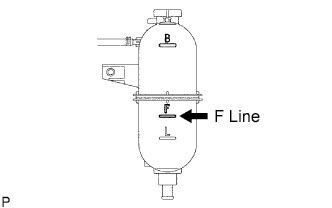
After the coolant cools down, check that the coolant level is at the F line.
If the coolant level is below the F line, add TOYOTA SLLC to the F line.
-
-
INSPECT FOR OIL LEAK
-
CHECK ENGINE OIL LEVEL
-
INSPECT FOR COOLANT LEAK
Note
Do not remove the radiator reservoir cap while the engine and radiator are still hot. Pressurized, hot engine coolant and steam may be released and cause serious burns.
-
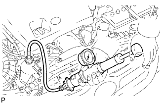
Fill the radiator with coolant and attach a radiator cap tester to the radiator reservoir.
-
Warm up the engine.
-
Using a radiator cap tester, increase the pressure inside the radiator to 118 kPa (1.2 kgf/cm2, 17.1 psi), and check that the pressure does not drop.
If the pressure drops, check the hoses, radiator and water pump for leaks.
If no external leaks are found, check the cylinder block and head.
-
-
INSTALL NO. 2 ENGINE UNDER COVER (for 4WD)
-
Install the No. 2 engine under cover with the 2 bolts.
- Torque:
- 28 N*m { 286 kgf*cm, 21 ft.*lbf }
-
-
INSTALL NO. 1 ENGINE UNDER COVER (for 4WD)
-
Install the No. 1 engine under cover with the 4 bolts.
- Torque:
- 28 N*m { 286 kgf*cm, 21 ft.*lbf }
-
-
PERFORM INITIALIZATION
-
Perform initialization Click here.
Note
Certain systems need to be initialized after disconnecting and reconnecting the cable from the negative (-) battery terminal.
-