SLIDING ROOF HOUSING INSTALLATION
PROCEDURE
-
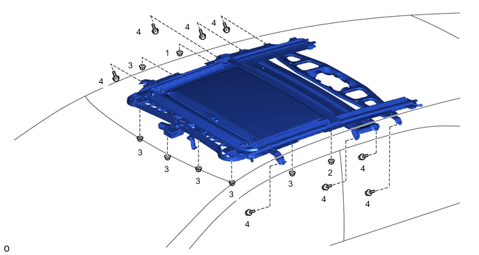
INSTALL SLIDING ROOF HOUSING SUB-ASSEMBLY
-
Temporarily install the sliding roof housing sub-assembly with the 8 bolts and 8 nuts.
-
Tighten the nuts in the order indicated in the illustration.
- Torque:
- 8.0 N*m { 82 kgf*cm, 71 in.*lbf }
-
Insert the sliding roof drain hose.
Note
Make sure the sliding roof drain hose is securely inserted to prevent water leakage.
-
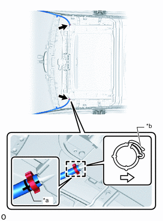
*a Marking *b Lock Portion of Clip 
Rear of Vehicle Attach the claw to install the front sliding roof drain hose clamps as shown in the illustration.
Note
-
Install the clip on the sliding roof housing sub-assembly side of the marking.
-
Make sure that the lock portion of the clip is facing the rear of the vehicle.
-
Make sure that the marking on the sliding roof drain hose is facing the bottom of the vehicle.
Tech Tips
Use the same procedure for both front sliding roof drain hose clamps.
-
-
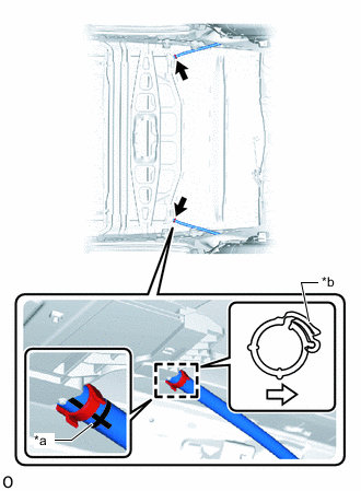
*a Marking *b Lock Portion of Clip Inside of Vehicle Attach the claw to install the rear sliding roof drain hose clamps as shown in the illustration.
Note
-
Install the clip on the sliding roof housing sub-assembly side of the marking.
-
Make sure that the lock portion of the clip is facing toward the inside of the vehicle.
-
Make sure that the marking on the sliding roof drain hose is facing the bottom of the vehicle.
Tech Tips
Use the same procedure for both rear sliding roof drain hose clamps.
-
-
-
INSTALL REAR SIDE RAIL SPACER LH
-
INSTALL REAR SIDE RAIL SPACER RH
Tech Tips
Use the same procedure described for the LH side.
-
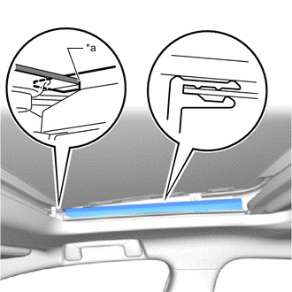
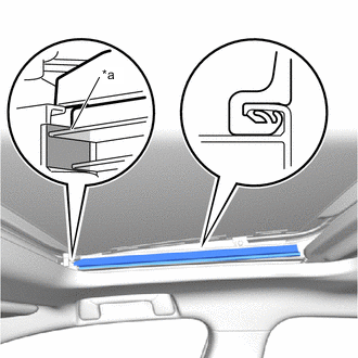
INSTALL SLIDING ROOF WEATHERSTRIP
-
Install the sliding roof weatherstrip as follows:
-
Align the marks on the sliding roof weatherstrip with the outside marks at the corners of the sliding roof panel sub-assembly and install the sliding roof weatherstrip.
Tech Tips
After installing, the sliding roof weatherstrip marking must be within the range between the inside and outside markings at each of the corners.
-
Install the lip of the sliding roof weatherstrip firmly.
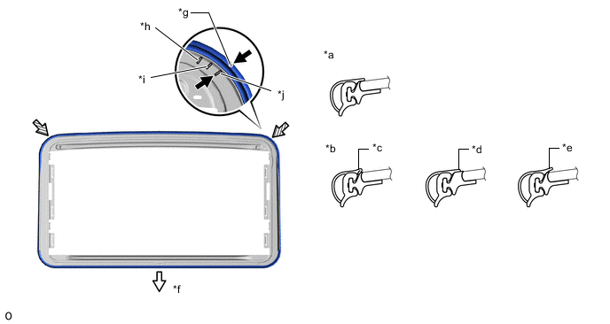
*a Normal *b Abnormal *c Pinched *d Exposed *e Gap (raised, wavy, etc.) *f Vehicle Rear *g Alignment Mark *h Inside Mark *i Middle Mark *j Outside Mark
-
-
-
INSTALL SLIDING ROOF GLASS SUB-ASSEMBLY
-
Using a T25 "TORX" socket wrench, temporarily install the sliding roof glass sub-assembly with the 4 screws.
-
Perform a level check.
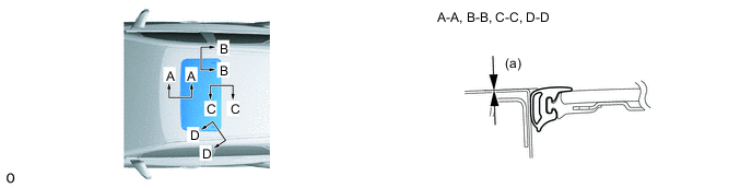
-
Check the difference in level for "a" between the roof panel and the upper surface of the weatherstrip when the sliding roof glass is fully closed.
Standard Area Measurement A - A 0 + 1.0 mm (0 + 0.0394 in.)
0 - 1.0 mm (0 - 0.0394 in.)
B - B 0 + 1.0 mm (0 + 0.0394 in.)
0 - 1.0 mm (0 - 0.0394 in.)
C - C 0 + 1.0 mm (0 + 0.0394 in.)
0 - 1.0 mm (0 - 0.0394 in.)
D - D 0 + 1.0 mm (0 + 0.0394 in.)
0 - 1.0 mm (0 - 0.0394 in.)
Tech Tips
"+" represents the condition that the glass is above the panel level. "-" represents the condition that the glass is below the panel level.
-
-
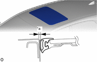
*a Even Perform a gap check.
-
Check the gap between the roof panel and roof glass.
Note
The gap must be even all around.
-
-
After adjusting the sliding roof glass, using a T25 "TORX" socket wrench, install the sliding roof glass sub-assembly with the 4 screws.
- Torque:
- 4.0 N*m { 41 kgf*cm, 35 in.*lbf }
-
-
CHECK FOR WATER LEAK
-
After adjusting the sliding roof glass sub-assembly, check for water leakage into the vehicle interior.
-
If there are any leaks, readjust the sliding roof glass sub-assembly.
-
-
INSTALL CURTAIN SHIELD AIRBAG ASSEMBLY LH
-
INSTALL CURTAIN SHIELD AIRBAG ASSEMBLY RH
Tech Tips
Use the same procedure described for the LH side.
-
INSTALL NO. 1 SLIDING ROOF SIDE GARNISH RH
-
*a Edge of the No. 1 Sliding Roof Side Garnish RH 
Installation Reference Surface. Attach the claw to install the No. 1 sliding roof side garnish RH.
Tech Tips
Align the edge of the No. 1 sliding roof side garnish RH with the installation reference surface.
-
-
INSTALL NO. 1 SLIDING ROOF SIDE GARNISH LH
Tech Tips
Use the same procedure described for the RH side.
-
INSTALL NO. 2 SLIDING ROOF SIDE GARNISH RH
-
*a Edge of the No. 2 Sliding Roof Side Garnish RH Installation Reference Surface. Attach the claw to install the No. 2 sliding roof side garnish RH.
Tech Tips
Align the edge of the No. 2 sliding roof side garnish RH with the installation reference surface.
-
-
INSTALL NO. 2 SLIDING ROOF SIDE GARNISH LH
Tech Tips
Use the same procedure described for the RH side.
-
CONNECT CABLE TO NEGATIVE BATTERY TERMINAL
Note
When disconnecting the cable, some systems need to be initialized after the cable is reconnected.
-
RESET SLIDING ROOF DRIVE GEAR SUB-ASSEMBLY
-
CHECK SLIDING ROOF SYSTEM
-
CHECK SRS WARNING LIGHT