AUTOMATIC TRANSMISSION ASSEMBLY (for 1GR-FE) INSTALLATION
-
INSPECT TORQUE CONVERTER CLUTCH ASSEMBLY
-
Inspect the torque converter clutch assembly Click here.
-
-
INSTALL TORQUE CONVERTER CLUTCH ASSEMBLY
-
Install the torque converter clutch to the automatic transmission.
-
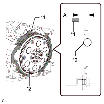
Using a vernier caliper and straightedge, measure dimension A between the surface of the engine that contacts the transmission*1, and the surface of the drive plate that contacts the converter*2. (#)
-
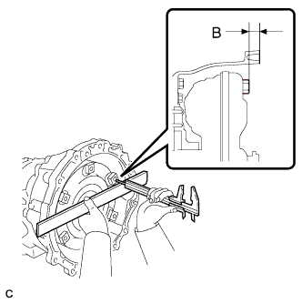
Using a vernier caliper and straightedge, measure dimension B shown in the illustration. Check that B is greater than A measured in step #.
Standard B = A + 1.00 mm (0.0394 in.) or more
-
-
INSTALL TRANSFER ASSEMBLY
-
Install the transfer assembly Click here.
-
-
INSTALL AUTOMATIC TRANSMISSION ASSEMBLY
-
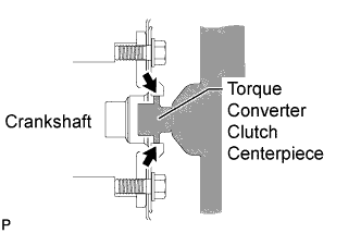
Apply clutch spline grease to the surface of the crankshaft that contacts the torque converter clutch centerpiece.
Clutch spline grease Toyota Genuine Clutch Spline Grease or equivalent Maximum grease amount Approximately 1.0 g (0.0353 oz) -
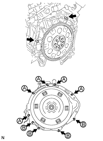
Install the transmission to the engine with the 9 bolts.
- Torque:
- for bolt A
- 71 N*m { 724 kgf*cm, 52 ft.*lbf }
- for bolt B
- 37 N*m { 377 kgf*cm, 27 ft.*lbf }
Note
Confirm that the 2 knock pins are installed to the surface of the engine block before installing the transmission..
-
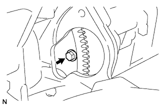
Hold the crankshaft pulley bolt with a wrench and install the 6 torque converter clutch setting bolts.
- Torque:
- 48 N*m { 489 kgf*cm, 35 ft.*lbf }
Tech Tips
First install the black bolt, and then the other 5 bolts.
-
-
INSTALL FLYWHEEL HOUSING SIDE COVER
-
Install the flywheel housing side cover to the cylinder block.
-
-
INSTALL STARTER ASSEMBLY
-
for 1.4 kW Type:
Install the starter assembly Click here.
-
for 1.6 kW Type:
Install the starter assembly Click here.
-
-
CONNECT WIRE HARNESS
-
Connect the park/neutral position switch connector.
-
Connect the transmission wire connector.
-
Connect the 2 speed sensor connectors.
-
Connect the No. 1 indicator switch connector.
-
Connect the No. 2 indicator switch connector.
-
Connect the No. 3 indicator switch connector.
-
Connect the speed sensor connector.
-
Attach the 7 wire harness clamps.
-
Connect the ground cable with the nut.
- Torque:
- 5.5 N*m { 56 kgf*cm, 49 in.*lbf }
-
-
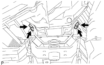
INSTALL REAR NO. 1 ENGINE MOUNTING INSULATOR
-
Install the engine mounting insulator to the transmission with the 4 bolts.
- Torque:
- 47 N*m { 479 kgf*cm, 35 ft.*lbf }
-
-
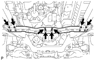
INSTALL NO. 3 FRAME CROSSMEMBER SUB-ASSEMBLY
-
Install the frame crossmember to the rear No. 1 engine mounting insulator with the 4 set bolts.
- Torque:
- 17 N*m { 173 kgf*cm, 13 ft.*lbf }
-
Connect the ends of the frame crossmember to the vehicle with the 4 bolts and 4 nuts.
- Torque:
- 50 N*m { 510 kgf*cm, 37 ft.*lbf }
-
-
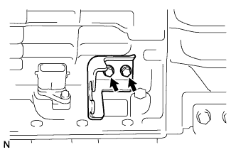
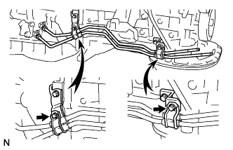
INSTALL NO. 1 TRANSMISSION CONTROL CABLE BRACKET
-
Install the control cable bracket with the 2 bolts.
- Torque:
- 14 N*m { 143 kgf*cm, 10 ft.*lbf }
-
-
INSTALL TRANSMISSION CONTROL CABLE ASSEMBLY
-
Connect the control cable with a new clip.
-
Connect the control cable with the nut.
- Torque:
- 14 N*m { 143 kgf*cm, 10 ft.*lbf }
-
-
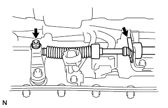
INSTALL OIL COOLER TUBE
-
Loosely install the tip of the inlet oil cooler tube to the automatic transmission by hand.
-
Loosely install the tip of the outlet oil cooler tube to the automatic transmission by hand.
-
Install the 2 clamps with the 2 bolts.
- Torque:
- 5.0 N*m { 50 kgf*cm, 43 in.*lbf }
-
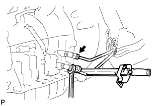
Using a union nut wrench, tighten the inlet and outlet oil cooler tubes.
- Torque:
- 34 N*m { 346 kgf*cm, 25 ft.*lbf }
Note
Use the formula to calculate special torque values for situations where a union nut wrench is combined with a torque wrench Click here.
-
-
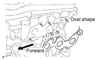
INSTALL EXHAUST MANIFOLD SUB-ASSEMBLY RH
-
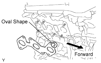
Set a new gasket to the RH cylinder head with the oval shape facing forward.
Note
Be careful of the installation direction.
-
Install the exhaust manifold with the 6 nuts. Uniformly tighten the nuts in several passes.
- Torque:
- 21 N*m { 214 kgf*cm, 15 ft.*lbf }
-
Connect the A/F sensor connector.
-
-
INSTALL EXHAUST MANIFOLD SUB-ASSEMBLY LH
-
Set a new gasket to the LH cylinder head with the oval shape facing backward.
Note
Be careful of the installation direction.
-
Install the exhaust manifold with the 6 nuts. Uniformly tighten the nuts in several passes.
- Torque:
- 21 N*m { 214 kgf*cm, 15 ft.*lbf }
-
Connect the A/F sensor connector.
-
-
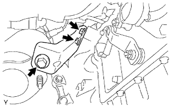
INSTALL NO. 2 MANIFOLD STAY
-
Install the manifold stay with the 3 bolts.
- Torque:
- 40 N*m { 408 kgf*cm, 30 ft.*lbf }
-
-
INSTALL MANIFOLD STAY
-
Install the manifold stay with the 3 bolts.
- Torque:
- 40 N*m { 408 kgf*cm, 30 ft.*lbf }
-
-
INSTALL PROPELLER SHAFT WITH CENTER BEARING ASSEMBLY
-
for TSAM Made:
Install the propeller shaft with center bearing assembly Click here.
-
for TMT Made:
Install the propeller shaft with center bearing assembly Click here.
-
-
INSTALL FRONT PROPELLER SHAFT ASSEMBLY
-
for TSAM Made:
Install the front propeller shaft assembly Click here.
-
for TMT Made:
Install the front propeller shaft assembly Click here.
-
-
INSTALL EXHAUST PIPE
-
Install the exhaust pipe Click here.
-
-
CONNECT HEATED OXYGEN SENSOR
-
Connect the 2 sensor connectors.
-
-
INSTALL TRANSFER HIGH AND LOW SHIFT LEVER ASSEMBLY
-
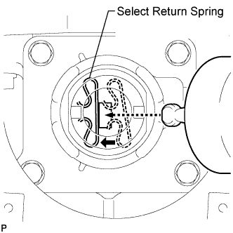
While pushing the select return spring to the left with the end of the transfer high and low shift lever, insert the end of the shift lever into the shift fork.
-
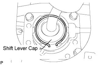
While holding down the shift lever cap, install the snap ring to install the transfer high and low shift lever.
-
Return the transfer front drive shift boot to its original position.
-
-
INSTALL SHIFT LEVER BOOT ASSEMBLY
-
Install the shift lever boot with the 4 screws.
-
-
INSTALL CONSOLE BOX ASSEMBLY
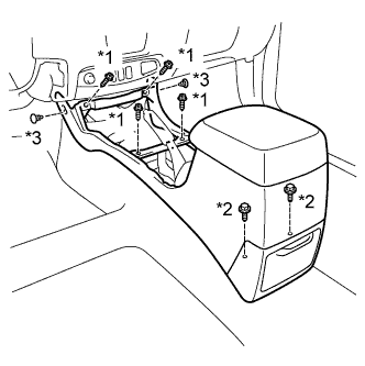
Text in Illustration *1 Screw *2 Bolt *3 Clip
-
Install the console box with the 4 screws and 2 bolts.
-
Install the 2 clips.
-
-
INSTALL UPPER CONSOLE PANEL SUB-ASSEMBLY
-
Attach the 12 claws to install the upper console panel.
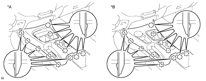
Text in Illustration *A for 2WD *B for 4WD
-
-
INSTALL PARKING BRAKE HOLE COVER SUB-ASSEMBLY
-
Attach the 4 claws to install the parking brake hole cover.
-
-
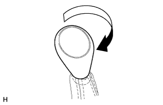
INSTALL SHIFT LEVER KNOB SUB-ASSEMBLY
-
Install the shift lever knob and twist it in the direction indicated by the arrow.
-
-
CONNECT CABLE TO NEGATIVE BATTERY TERMINAL
Note
Certain systems need to be initialized after disconnecting and reconnecting the cable to the negative (-) battery terminal.
-
ADD AUTOMATIC TRANSMISSION FLUID
-
Add automatic transmission fluid Click here.
-
-
INSPECT SHIFT LEVER POSITION
-
When moving the shift lever from P to R with the ignition switch ON and the brake pedal depressed, make sure that the shift lever moves smoothly and correctly into position.
-
Start the engine and make sure that the vehicle moves forward after moving the shift lever from N to D, and moves in reverse after shifting to R.
If the results are not as specified, inspect the park/ neutral position switch and check the shift lever.
-
-
PERFORM INITIALIZATION
-
Perform initialization Click here.
-
-
CHECK FOR EXHAUST GAS LEAKS
-
INSTALL NO. 3 ENGINE UNDER COVER
- Torque:
- 28 N*m { 285 kgf*cm, 21 ft.*lbf }
-
INSTALL NO. 2 ENGINE UNDER COVER
- Torque:
- 28 N*m { 285 kgf*cm, 21 ft.*lbf }
-
INSTALL NO. 1 ENGINE UNDER COVER
- Torque:
- 28 N*m { 285 kgf*cm, 21 ft.*lbf }